
Related Manuals for RoboteQ AX2550


Summary of Contents for RoboteQ AX2550
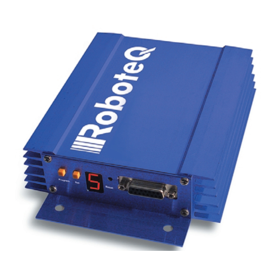
- Page 1 AX2550 AX2850 Dual Channel High Power Digital Motor Controller Quick Start Manual v1.9b, June 1, 2007 visit www.roboteq.com to download the latest revision of this manual ©Copyright 2003-2007 Roboteq, Inc.
-
Page 2: Important Safety Warnings
Warnings Read this Section First The AX2550 is a high power electronics device. Serious damage, including fire, may occur to the unit, motors, wiring and batteries as a result of its misuse. Please review the User’s Manual for added precautions prior to applying full battery or full load power. -
Page 3: Quick Start
Quick Start This section will give you the basic information needed to quickly install, setup and run your AX2550 controller in a minimal configuration. The AX2850 is a version of the AX2550 controller with the addition of Optical Encoder inputs. - Page 4 Motor (-) 12 to 40V (+) Ground (-) 12 to 40V (+) Motor(+) Motor (-) White Green Black Yellow or Green White Motor 1 Motor 2 FIGURE 2. Rear Controller Layout AX2550 Motor Controller User’s Manual Version 1.9b. June 1, 2007...
-
Page 5: Connecting To The Batteries And Motors
Typically, 1, 2 or 3 x 12V batteries are connected in series to reach 12, 24 or 36V respectively. The Power Control wire MUST be used to turn On and Off the controller. FIGURE 3. AX2550 Electrical Power Wiring Diagram 1- Connect each motor to one of the two M+ and M- cables pairs. Make sure to respect... -
Page 6: Important Warning
2A Digital Output C (same as pin 1) Analog Input 2 Analog Input 1 Analog Input 3 (on RevB hardware) Ground Out +5V Out (100mA max.) Emergency Stop or Invert Switch input AX2550 Motor Controller User’s Manual Version 1.9b. June 1, 2007... -
Page 7: Connecting The R/C Radio
FIGURE 4. R/C connector wiring for 3 channels and battery elimination (BEC) This wiring - with the wire loop uncut - assumes that the R/C radio will be powered by the AX2550 controller. Other wiring options are described in “R/C Operation” on page 109 of the User’s Manual. -
Page 8: Powering On The Controller
R/C mode. Button Operation The AX2550 has three buttons: Set, Program and Reset. These buttons are not needed for normal operation, as the controller is immediately operational upon power up. The Reset button will restart the controller. This button is recessed and you will need a paper clip to press it. -
Page 9: Default Controller Configuration
The example below shows how to use the buttons to select and change the Motor Control mode from “separate” to “mixed” . See “Configuring the Controller using the Switches” on page 171 of the User’s Manual for a complete list of all the AX2550’s parameters and their meanings. -
Page 10: Connecting The Controller To Your Pc Using Roborun
• to read and plot real-time current consumption value • Save captured parameters onto disk for later analysis • to update the controller’s software AX2550 Motor Controller User’s Manual Version 1.9b. June 1, 2007... -
Page 11: Obtaining The Controller's Software Revision Number
Obtaining the Controller’s Software Revision Number One of the unique features of the AX2550 is the ability to easily update the controller’s operating software with new revisions downloaded from Roboteq’s web site at www.roboteq.com. This is useful for adding features and/or improving existing ones. -
Page 12: Exploring Further
Now that you know your controller’s software version number, you will be able to see if a new version is available for download and installation from Roboteq’s web site and which features have been added or improved. Installing new software is a simple and secure procedure, fully described in “Updating the Controller’s Software”...
Need help?
Do you have a question about the AX2550 and is the answer not in the manual?
Questions and answers