Table of Contents
Advertisement
Advanced Features
2 x 60A or 1 x 120A
Brushless DC
Motor Controller
with USB and CAN
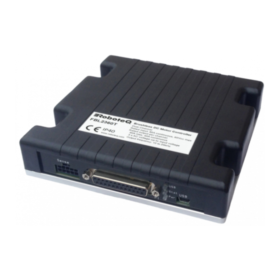
RoboteQ's FBL2360 is a features-packed, high-current, dual
or single channel controller for brushless DC motors. The
controller can operate in one of several modes in order to
sense the rotor position and sequence power on the motor's
3 windings in order to generate smooth continuous rotation.
The controller also uses the Hall sensor and/or Encoder
information to compute speed and measure travelled distance
inside a 32-bit counter. The motors may be operated in open
or closed loop speed mode, position mode or in torque mode.
The FBL2360 features several Analog, Pulse and Digital I/
Os which can be remapped as command or feedback inputs,
limit switches, or many other functions. The FBL2360 accepts
commands received from an RC radio, Analog Joystick,
wireless modem, or microcomputer. For mobile robot
applications, the controller's two motor channels can either be
operated independently or mixed to move and steer a vehicle.
Using CAN bus, up to 127 controllers can be networked at up
to 1Mbit/s on a single twisted pair.
Numerous safety features are incorporated into the controller to
ensure reliable and safe operation. The controller's operation can
be extensively automated and customized using Basic Language
scripts. The controller can be configured, monitored and tuned
in real-time using a RoboteQ's free PC utility. The controller can
also be reprogrammed in the field with the latest features by
downloading new operating software from Roboteq.
Applications
Automatic Guided Vehicles
•
Small Electric Vehicles, Electric Bikes
•
Terrestrial and Underwater Robotic Vehicles
•
Police and Military Robots
•
Hazardous Material Handling Robots
•
Balancing Robots
•
Telepresence Systems
•
Animatronics
•
FBL2360 Brushless DC Motor Controller Datasheet
Key Features
USB, Serial, 0-5V Analog, or Pulse (RC radio) command
•
modes
One RS232 serial port
•
CAN bus interface up to 1Mbit/switch multiple protocol
•
support
RS485
•
Optional Ethernet interface
•
Auto switch between Serial, USB, CAN, Analog, or
•
Pulse based on user-defined priority
Built-in dual 3-phase high-power drivers for two
•
brushless DC motor at up to 60A
Output channels can be paralleled in order to drive a
•
single motor at up to 120A
Multiple Motor Operating mode
•
- Trapezoidal with Hall Sensors
- Sinusoidal with Encoders
- Sinusoidal with Hall Sensors
Support for absolute angle encoders
•
sin/cos analog
•
SSI (A & T version)
•
Resolver (A & T version)
•
Field Oriented Control in Sinusoidal modes
•
Full forward & reverse motor control. Four quadrant
•
operation. Supports regeneration
Operates from a single 10V-60V power source
•
STO - Safe Torque Off support (T-version) - Certification
•
No. M6A 104504 0001 Rev. 00
Design compliant/approval UL 61800-5-1
•
Programmable current limit up to 60A (120Aon single
•
channel version) per motor for protecting controller,
motor, wiring and battery.
Separate connector for Hall Sensors
•
Accurate speed and Odometry measurement using
•
Hall Sensor or Encoder data
FBL2360
1
Advertisement
Table of Contents

Related Manuals for RoboteQ FBL2360


Summary of Contents for RoboteQ FBL2360
- Page 1 The controller can be configured, monitored and tuned Resolver (A & T version) • in real-time using a RoboteQ’s free PC utility. The controller can Field Oriented Control in Sinusoidal modes • also be reprogrammed in the field with the latest features by Full forward &...
-
Page 2: Orderable Product References
Controller is designed and build to comply with UL and IEC specifications and standards, but is approved only under the mentioned standards on this datasheet. Orderable Product References Reference Number of Channels Amps/Channel Volts Ethernet FBL2360(A) FBL2360(A)S FBL2360T FBL2360TS FBL2360E FBL2360ES FBL2360TE FBL2360TES FBL2360 Brushless DC Motor Controller Datasheet Version 1.3 August 29, 2019... -
Page 3: Power Wires Identifications And Connection
The user must assume that such failures can occur and must make his/her system safe in all conditions. Roboteq will not be liable in case of damage or injury as a result of product misuse or failure. -
Page 4: Important Warning
Electrostatic Discharge Protection In accordance with IEC 61000-6-4, Roboteq Motor Controllers are designed to withstand ESD up to 4kV touch and 8kV air gap. This protection is implemented without any additional external connections required. -
Page 5: Precautions And Optional Connections
This wiring must be done only on the single channel version of the controller. Paralleling the wires on a dual channel product will cause permanent damage. Verify that your controller is an FBL2360S before you wire in this manner. FBL2360 Brushless DC Motor Controller Datasheet... -
Page 6: Controller Mounting
Connection to the Hall Sensors is done using a special connector on the front side of the controller. The Hall sensor connector is a 10-pin Molex Microfit 3.0, ref. 43025-1000. Pin assignment is in the table below. FIGURE 6. Hall Sensors connector FBL2360 Brushless DC Motor Controller Datasheet Version 1.3 August 29, 2019... - Page 7 FIGURE 7 . Hall Sensors sequence Connection to SPI Absolute Encoder In Sinusoidal Mode, the FBL2360 and FBL2360S models can use motors equipped with absolute angle sensors with SPI interface, such as found on the BL167 or BL90 motors from Micromotor. When enabled, the SPI signals are found on the 10-pin Molex connector that is otherwise used for the Hall Sensors.
- Page 8 Data 1 + Connection to Analog Sin/Cos Absolute Encoder The FBL2360 has 4 high-speed analog inputs that can be used to capture absolute angle position from resolvers or magnetic sensors with sin/cos voltage outputs. The signal must be 0-5V max with the 0 at 2.500V. The table below shows the signals assignment on the 25-pin connector.
- Page 9 DB25 connector. The functions of many pins vary depending on controller model and user configuration. Pin assignment is found in the table below. FIGURE 9. Main Connector pin locations FBL2360 Brushless DC Motor Controller Datasheet...
-
Page 10: Default I/O Configuration
The figure below shows how to wire the controller to two analog potentiometers, an RC radio, and the RS232 port. It also shows FBL2360 Brushless DC Motor Controller Datasheet Version 1.3 August 29, 2019... -
Page 11: Usb Communication
Always prefer RS232 communication when interfacing to a computer. USB and CAN can operate at the same time on the FBL2360. Plugging USB to a computer will not disable CAN interface. -
Page 12: Ethernet Communication
Ethernet communication is currently only available on the E versions of applicable Roboteq product. There is a connection port on the top of the unit for easy and rapid access. While the TCP and Modbus TCP protocols are supported, Serial is the preferred method to access all native commands. - Page 13 The controller includes Amps sensors in line with the motor terminals. Motor Amps are measured with precision. Battery Amps are estimated mathematically. When motor is rotating, amps are AC. The FBL2360 measures and is rated based on RMS Amps. The table below shows the relation between the RMS current and the DC Equivalent in Sinusoidal and Trapezoidal modes.
-
Page 14: Electrical Specifications
Note 1: Can be even higher because of regeneration voltage. Never inject a DC voltage from a battery or other fixed source Note 2: No voltage must be applied on Tx pin Note 3: Non condensing FBL2360 Brushless DC Motor Controller Datasheet Version 1.3 August 29, 2019... - Page 15 Note 9: Controller will stop until restarted in case of short circuit detection” change with “Controller will stop until zero command given in case of short circuit detection Note 10: Approximate value Note 11: Factory default value. Time in ms for power to go from 0 to 100% FBL2360 Brushless DC Motor Controller Datasheet...
-
Page 16: Command, I/O And Sensor Signals Specifications
Bits/s RS232 Watchdog timeout Rx pin 1 (2) 65000 Note 1: 115200, 8-bit, no parity, 1 stop bit, no flow control Note 2: May be disabled with value 0 FBL2360 Brushless DC Motor Controller Datasheet Version 1.3 August 29, 2019... -
Page 17: Thermal Specifications
2 x 40A fuse should be installed. Power source must be capable to blow the fuse instantly in case of short circuit Note 5: Current limiting mechanism available through firmware. External overload motor protection can be used if required (provided by user) FBL2360 Brushless DC Motor Controller Datasheet... -
Page 18: Sto Specifications
Power Connectors width Terminal tab 0.25 Inches 0.98" 0.25" (25mm) (6.3 mm) 0.7" (17.8mm) 0.57" 0.3" (14.5mm) (7.6 mm) 0.16" (4.0mm) 0.325" (8.3 mm) FIGURE 14. FBL2360 side view and dimensions FBL2360 Brushless DC Motor Controller Datasheet Version 1.3 August 29, 2019... -
Page 19: Revision History
Electrical Specifications 5.50" (139.7mm) 0.24" (6.0mm) 1.25" (31.8mm) 3.00" (76.2mm) FIGURE 15. FBL2360 top view and dimensions Revision history Revision Date Additions/Changes Hall Sensors I/O Connector LEDs April 23, 2019 Added T-version with STO support Connector Connector May 21, 2019...
Need help?
Do you have a question about the FBL2360 and is the answer not in the manual?
Questions and answers