
Subscribe to Our Youtube Channel
Related Manuals for RoboteQ AX500


Summary of Contents for RoboteQ AX500
- Page 1 AX500 Dual Channel Digital Motor Controller Quick Start Manual v1.9b, June 1, 2007 visit www.roboteq.com to download the latest revision of this manual ©Copyright 2003-2007 Roboteq, Inc.
-
Page 2: Important Safety Warnings
Warnings Read this Section First The AX500 is a power electronics device. Serious damage, including fire, may occur to the unit, motors, wiring and batteries as a result of its misuse. Please review the User’s Manual for added precautions prior to applying full battery or full load power. -
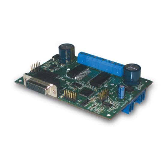
Page 3: Quick Start
AX500 SECTION 2 Quick Start This section will give you the basic information needed to quickly install, setup and run your AX500 controller in a minimal configuration. What you will need For a minimal installation, gather the following components: •... - Page 4 Connector to Receiver/ Controls and sensors Status LED FIGURE 1. AX500 Controller Front View At the back of the controller (shown in the figure below) are located all the that must be connected to the batteries and the motors. Note:...
-
Page 5: Connecting To The Batteries And Motors
Typically, 1 or 2 x 12V batteries are connected in series to reach 12 or 24V respectively. FIGURE 3. AX500 Electrical Power Wiring Diagram 1- Connect each motor to one of the two M+ and M- terminal pairs. Make sure to respect the polarity, otherwise the motor(s) may spin in the opposite direction than expected two of the three Ground terminals2- Connect the VCon terminal (powering the controller’s... -
Page 6: Connecting To The 15-Pin Connector
When operating the controller in “Mixed” mode, Ch1 is used to set the robot’s speed and direction, while Ch2 is used for steering. See “R/C Operation” on page 81 of the User’s Manual for a more complete discussion on R/C commands, calibration and other options. AX500 Motor Controller User’s Manual Version 1.9b. June 1, 2007... -
Page 7: Powering On The Controller
FIGURE 4. R/C connector wiring for 3 channels and battery elimination (BEC) This wiring - with the wire loop uncut - assumes that the R/C radio will be powered by the AX500 controller. Other wiring options are described in “R/C Operation” on page 81 of the User’s Manual. -
Page 8: Default Controller Configuration
FIGURE 5. Status LED Flashing pattern during normal operation Default Controller Configuration Version 1.9b of the AX500 software is configured with the factory defaults shown in the table below. Although Roboteq strives to keep the same parameters and values from one version to the next, changes may occur from one revision to the next. -
Page 9: Obtaining The Controller's Software Revision Number
Obtaining the Controller’s Software Revision Number One of the unique features of the AX500 is the ability to easily update the controller’s oper- ating software with new revisions downloaded from Roboteq’s web site at www.roboteq.com. -
Page 10: Exploring Further
PC connection discussed previously. Now that you know your controller’s software version number, you will be able to see if a new version is available for download and installation from Roboteq’s web site and which features have been added or improved.
Need help?
Do you have a question about the AX500 and is the answer not in the manual?
Questions and answers