Table of Contents
Advertisement
Quick Links
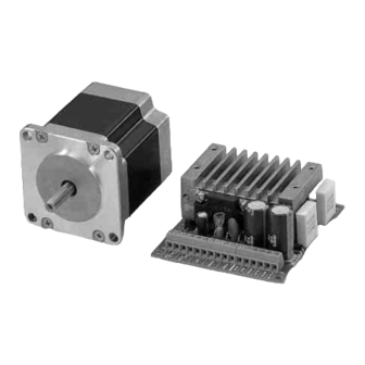
2-Phase Stepping Motor Unit
CSK Series
OPERATING MANUAL
Thank you for purchasing an Oriental Motor product.
This operating manual describes product handling procedures and safety precautions.
Please read it thoroughly to ensure safe operation.
•
Always keep the manual where it is readily available.
•
Table of contents
1 Introduction .................................. 2
2 Safety precautions ....................... 5
3 Precautions for use ...................... 8
4 Preparation................................. 10
4.1
Checking the product ................ 10
4.2
drivers ....................................... 10
4.3
5 Installation .................................. 15
5.1
Location for installation ............. 15
5.2
Installing the motor.................... 15
5.3
Installing a load ......................... 17
5.4
permissible thrust load .............. 18
5.5
Installing the driver.................... 19
5.6
with EMC Directive.................... 20
6 Connection..................................23
6.1
CSD2112-T, CSD2120-T........... 23
6.2
CSD2145T ................................ 26
6.3
About input/output .................... 28
6.4
Timing chart.............................. 32
7 Setting.........................................33
7.1
function..................................... 33
7.2
Step angle ................................ 34
7.3
Pulse input mode...................... 34
7.4
Power supply voltage ............... 35
7.5
Motor currents .......................... 35
8 Inspection....................................44
actions ........................................45
HP-7443-3
Advertisement
Table of Contents

Related Manuals for Orientalmotor CSK243-ATA


Summary of Contents for Orientalmotor CSK243-ATA
-
Page 1: Table Of Contents
HP-7443-3 2-Phase Stepping Motor Unit CSK Series OPERATING MANUAL Thank you for purchasing an Oriental Motor product. This operating manual describes product handling procedures and safety precautions. Please read it thoroughly to ensure safe operation. • Always keep the manual where it is readily available. •... -
Page 2: Introduction
1 Introduction 1 Introduction Before use Only qualified personnel should work with the product. Use the product correctly after thoroughly reading the section “Safety precautions”. The product described in this manual has been designed and manufactured for use in general industrial machinery, and must not be used for any other purpose. Oriental Motor Co., Ltd. - Page 3 1 Introduction System configuration Operating the CSK series requires a controller equipped with a pulse output function. Controller Driver Motor Digital I/O DC power input As for the voltage supply to the driver, use an EMC-compliant DC power supply with reinforced insulation on both the primary and secondary sides. Compliance with the EC Directives If compliance with the European Low Voltage Directive and EMC Directive is required, the user is advised to take full responsibility for the following measures:...
- Page 4 1 Introduction • For EMC Directive (89/336/EEC, 92/31/EEC) This product has received EMC measures under the conditions specified in “Example of motor and driver installation and wiring” on page 22. Be sure to conduct EMC measures with the product assembled in your equipment by referring to 5.6 “Installing and wiring in compliance with EMC Directive”...
-
Page 5: Safety Precautions
2 Safety precautions 2 Safety precautions The precautions described below are intended to prevent danger or injury to the user and other personnel through safe, correct use of the product. Use the product only after carefully reading and fully understanding these instructions. Handling the product without observing the instructions that Warning accompany a “Warning”... - Page 6 2 Safety precautions Operation • Turn off the driver power in the event of a power failure, or the motor may suddenly start when the power is restored and may cause injury or damage to equipment. • Do not turn the C.OFF (all windings off) input to “ON” while the motor is operating.
- Page 7 2 Safety precautions • To prevent bodily injury, do not touch the rotating parts (output shaft) of the motor during operation. • Immediately when trouble has occurred, stop running and turn off the driver power. Failure to do so may result in fire, electric shock or injury. Disposal •...
-
Page 8: Precautions For Use
3 Precautions for use 3 Precautions for use This section covers limitations and requirements the user should consider when using the CSK series. • Do not apply an overhung load and thrust load in excess of the specified permissible limit. Be sure to operate the motor within the specified permissible limit of overhung load and thrust load. - Page 9 3 Precautions for use • Maximum static torque at excitation The maximum static torque at excitation represents the torque when the motor is excited at the rated current. If the motor is combined with a dedicated driver, the automatic current cutback function reduces the maximum static torque at excitation to around 40%.
-
Page 10: Preparation
This is to prevent damage to the driver due to static electricity. 4.2 Combinations of motors and drivers Standard type Unit model Motor model Driver model CSK243-ATA PK243-01AA CSD2109-T CSK243-BTA PK243-01BA CSK244-ATA PK244-01AA... - Page 11 4 Preparation Unit model Motor model Driver model CSK296-ATA PK296-03AA CSK296-BTA PK296-03BA CSD2145T CSK299-ATA PK299-03AA CSK299-BTA PK299-03BA CSK2913-ATA PK2913-02AA CSD2140T CSK2913-BTA PK2913-02BA High resolution type Unit model Motor model Driver model CSK243MATA PK243MAA CSD2109-T CSK243MBTA PK243MBA CSK244MATA PK244MAA CSK244MBTA PK244MBA CSD2112-T CSK245MATA PK245MAA...
-
Page 12: Names And Functions Of Driver
4 Preparation 4.3 Names and functions of driver This section covers the names and functions of parts in the driver. CSD2109-T, CSD2112-T, CSD2120-T Mounting holes Name Description I/O and power supply terminal Connected to I/O signals and a 24 VDC or blocks (TB1) 36 VDC power supply. - Page 13 4 Preparation Name Description Potentiometer for adjusting the This potentiometer sets the current when the motor standstill current motor is at a standstill (in the current cutback (STOP VR) state). Factory setting: 40% of the rated current Positive check terminal for This terminal is used to check the motor motor operating current (C.C.+) operating current.
- Page 14 4 Preparation Name Description Step angle jumper socket This switch sets the motor’s step angle (full (FULL/HALF) step/half step). Factory setting: [FULL] (full step) −14−...
-
Page 15: Installation
5 Installation 5 Installation This chapter explains the installation location and installation methods of the motor and driver, as well as how to install a load. The installation and wiring methods in compliance with the EMC Directive are also explained. 5.1 Location for installation The motor and driver are designed and manufactured for installation in equipment. - Page 16 5 Installation • Installation method A • Installation method B Mounting hole Mounting hole Pilot holder Pilot holder Metal plate Metal plate Installation method C Installation method D • • Mounting hole Gearhead- attaching screw Mounting hole Pilot holder Pilot holder Metal plate Metal plate Cross-recessed pan...
-
Page 17: Installing A Load
5 Installation 5.3 Installing a load When connecting a load to the motor, align the centers of the motor’s output shaft and load shaft. Also, keep the overhang load and thrust load to the permissible values or below. • Using a coupling Align the centers of the motor’s output shaft and load shaft in a straight line. -
Page 18: Permissible Overhung Load And Permissible Thrust Load
5 Installation 5.4 Permissible overhung load and permissible thrust load The overhung load on the motor’s output shaft or gear output shaft must be kept within the permissible values listed below. Failure due to fatigue may occur if the motor’s bearings and output shaft Note are subject to repeated loading by an overhung or thrust load that is in excess of the permissible limit. -
Page 19: Installing The Driver
5 Installation 5.5 Installing the driver When installing the driver in an enclosure, be sure to follow the diagram illustrated. Provide a minimum clearance of 25 mm (1 in.) in the horizontal direction or 50 mm (2 in.) in the vertical direction between the driver and enclosure or other equipment within the enclosure. -
Page 20: Installing And Wiring In Compliance With Emc Directive
5 Installation CSD2140T, CSD2145T Mount the driver to the mounting plate using No.4-40 UNC screws. • Horizontal installation • Vertical installation No.4-40 UNC Mounting screw plate No.4-40 UNC screw Mounting plate 5.6 Installing and wiring in compliance with EMC Directive Effective measures must be taken against the EMI that the CSK series may give to adjacent control-system equipment, as well as the EMS of the CSK series itself, in order to prevent a serious functional impediment in the machinery. - Page 21 5 Installation • Connecting mains filter for power supply line Connect a mains filter in the AC input line to prevent the noise generated in the driver from propagating externally through the power supply line. Use a mains filter or equivalent as below table. Manufacture Product number Tyco Electronics CORCOM...
- Page 22 5 Installation • Example of motor and driver installation and wiring Motor User Driver controller Motor cable [2 m (6.6 in.)] Cable Cable I/O cable clamp clamp [2 m (6.6 in.)] Mains DC power filter supply Power supply (Shielded cable) Cable cable clamp...
-
Page 23: Connection
6 Connection 6 Connection This section covers the methods and examples of connecting and grounding the driver, motor, power and controller, as well as the control input/output. 6.1 Connection of CSD2109-T, CSD2112-T, CSD2120-T Connection example Either 24 VDC or 36 VDC is selected as a driver’s power supply. Be sure to check the setting of the power supply voltage switch. - Page 24 6 Connection Be certain the control input/output cable that connects the driver and Note • controller is as short as possible. The maximum input frequency will decrease as the cable length increases. When a large inertial load is operated at high speed, regenerative •...
- Page 25 6 Connection • Terminal blocks pin assignments (TB1) Signal name Description POWER+ DC power supply input POWER− TIMING+ output Excitation timing output TIMING− output A.W.OFF+ input All windings off input A.W.OFF− input DIR./CCW+ input ∗ Rotation direction (CCW pulse) input DIR./CCW−...
-
Page 26: Connection Of Csd2140T, Csd2145T
6 Connection 6.2 Connection of CSD2140T, CSD2145T Connection example The driver’s power supply voltage should be 24 VDC. Driver +24 V 2-phase stepping motor Blue Green Black Controller Controller Yellow PNP type NPN type White +5 V +5 V 220 Ω PLS+ PLS- 220 Ω... - Page 27 6 Connection Connecting the power supply Connecting the power supply wires into the driver’s power supply terminal blocks (TB1). Screw terminals are used. Remove the insulation from the core, then insert the core into the terminal and tighten with terminal screws. Strip 5 mm (0.2 in.) of insulation.
-
Page 28: About Input/Output
6 Connection Connecting the I/O Connecting the I/O signal wires into the driver’s I/O terminal blocks (TB3). Screw terminals are used. Remove the insulation from the core, then insert the core into the terminal and tighten with terminal screws. Strip 5 mm (0.2 in.) of insulation. Tighten the terminal screw to the specified tightening torque. - Page 29 6 Connection • PLS (CW pulse) input and DIR (CCW pulse) input CSD2109-T, CSD2112-T and CSD2120-T can select either 1-pulse input mode or 2-pulse input mode as the pulse input mode to match the controller used. For details on how to set the pulse input mode, see 7.3 “Pulse input mode” on page 34. The direction of rotation indicates the direction in which the motor’s output shaft rotates, as viewed from the motor mounting surface.
- Page 30 6 Connection 2-pulse input mode The controller’s CW pulses are connected to the CW+ or the CW−, while the CCW pulses are connected to the CCW+ or the CCW−. • When the CW pulse input changes from the ON to OFF, the motor will rotate one step in the CW direction.
- Page 31 6 Connection Output signals Driver output signals are photocoupler/open-collector output. The signal state represents the “ON: Carrying current” or “OFF: Not carrying current” state of the internal photocoupler rather than the voltage level of the signal. Controller output Driver internal circuits TIMING 10 mA or less Use an output signal voltage of 5 VDC minimum and 24 VDC maximum, and use...
-
Page 32: Timing Chart
6 Connection When using the TIM output, stop the motor’s output shaft at an integer Note • multiple of 7.2°. When switching the step angle, do this with the motor stopped and the • TIM output ON. When the power is turned ON, the excitation sequence is reset to STEP •... -
Page 33: Setting
7 Setting 7 Setting This section covers the selection and settings of driver functions. Be sure to shut off the power before using the resolution select switch. Note • The new resolution takes effect when the power is turned on again. The driver may malfunction or become damaged due to the effects of •... -
Page 34: Step Angle
7 Setting 7.2 Step angle Set the step angle of the motor using the step angle switch (jumper socket). CSD2109-T, CSD2112-T, CSD2120-T CSD2140T, CSD2145T Step angle switch (F/H) Step angle jumper socket (FULL /HALF) Factory setting: ON (full step) Factory setting: FULL (full step) •... -
Page 35: Power Supply Voltage
7 Setting 7.4 Power supply voltage (Only for CSD2109-T, CSD2112-T, CSD2120-T) Be sure to set the power supply voltage switch 24/36V (24/36V) according to the driver’s power supply input voltage. Factory setting: 24V ON: 24 V • Set the switch to ON when the power supply OFF: 36 V voltage is 24 VDC. - Page 36 7 Setting Setting method for CSD2109-T, CSD2112-T, CSD2120-T An ammeter or tester is needed to set the motor current. Note that a tester is required only for the CSD2109-T, CSD2112-T and CSD2120-T. • Connecting an ammeter or tester Connecting an ammeter: Connect the driver, motor and DC ammeter.
- Page 37 7 Setting • Adjusting the motor operating current Set the step angle switch (F/H) to ON (full step). ON: full step OFF: half step Set the automatic current cutback function switch (ACD) to OFF (disable). ON: enable Turn on the power supply. OFF: disable Wait until the motor reaches its operating current.
- Page 38 7 Setting • Adjusting the motor standstill current Set the step angle switch (F/H) to ON (full step). ON: full step OFF: half step Set the automatic current cutback function switch (ACD) to ON (enable). ON: enable Turn on the power supply. OFF: disable Wait until the motor reaches its standstill current.
- Page 39 7 Setting Setting method for CSD2140T, CSD2145T • Connecting an ammeter Connect the driver, motor and DC ammeter. 2-phase stepping motor Motor leads color Driver TB2 Blue BLUE Green GREEN Black BLACK Yellow YELLOW White WHITE • Adjusting the motor operating current Set the jumper socket for the step angle switch (FULL/HALF) to FULL.
- Page 40 7 Setting • Adjusting the motor standstill current Set the jumper socket for the step angle switch (FULL/HALF) to FULL. Set the jumper socket for automatic current cutback function (C.C./A.C.D.) to A.C.D. Turn on the power supply. Wait until the motor reaches its standstill current. Using an insulated screwdriver, manipulate the potentiometer for adjusting the motor standstill current (STOP VR).
- Page 41 7 Setting • Current adjusting potentiometer The scale values are not displayed on the control. CSD2109-T, CSD2112-T, CSD2120-T CSD2140T, CSD2145T CSK243 Characteristic of motor operating current Characteristic of motor standstill current (representative value) (representative value) CSK243SG CSK243M 0.95 A/Phase 0.5 A/Phase 0.3 A/Phase Setting of the RUN potentiometer Setting of the STOP potentiometer...
- Page 42 7 Setting CSK264 Characteristic of motor operating current Characteristic of motor standstill current (representative value) (representative value) CSK264SG CSK264M 2.0 A/Phase 1.0 A/Phase 0.5 A/Phase Setting of the RUN potentiometer Setting of the STOP potentiometer CSK266 Characteristic of motor operating current Characteristic of motor standstill current (representative value) (representative value)
- Page 43 7 Setting CSK299 Characteristic of motor operating current Characteristic of motor standstill current (representative value) (representative value) 4.5 A/Phase 2.3 A/Phase 1.2 A/Phase Setting of the RUN potentiometer CSK2913 Characteristic of motor operating current Characteristic of motor standstill current (representative value) (representative value) 4.0 A/Phase 2.0 A/Phase...
-
Page 44: Inspection
8 Inspection 8 Inspection It is recommended that periodic inspections be conducted for the items listed below after each operation of the motor. If an abnormal condition is noted, discontinue any use and contact your nearest office. During inspection • Are any of the motor mounting screws loose? •... -
Page 45: Troubleshooting And Remedial Actions
9 Troubleshooting and remedial actions 9 Troubleshooting and remedial actions During motor operation, the motor or driver may fail to function properly due to an improper speed setting or wiring. When the motor cannot be operated correctly, refer to the contents provided in this section and take appropriate action. If the problem persists, contact your nearest office. - Page 46 9 Troubleshooting and remedial actions Phenomenon Possible cause Remedial action Loss of The centers of the motor’ Check the connection synchronization output shaft and load shaft are condition of the motor output during acceleration or not aligned. shaft and load shaft. running.
- Page 47 9 Troubleshooting and remedial actions Phenomenon Possible cause Remedial action Motor vibration too The centers of the motor’s Check the connection great. output shaft and load shaft are condition of the motor output not aligned. shaft and load shaft. Motor resonating If the vibration decreases when the operating pulse speed is changed, it means...
- Page 48 Oriental Motor is not liable whatsoever for the performance of these third-party products. © Copyright ORIENTALMOTOR CO., LTD. 2008 • Please contact your nearest Oriental Motor office for further information.