
Related Manuals for Fronius Agilo 75.0-3


Summary of Contents for Fronius Agilo 75.0-3
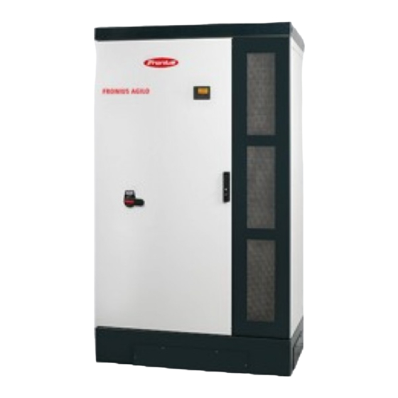
- Page 1 / Perfect Charging / Perfect Welding / Solar Energy Operating Instructions Fronius Agilo Outdoor 75.0-3 / 100.0-3 Grid-connected inverter 42,0426,0163,EN 005-03122014...
- Page 3 Thank you for the trust you have placed in our company and congratulations on buying this high-quality Fronius product. These instructions will help you familiarise yourself with the product. Reading the instructions carefully will enable you to learn about the many different features it has to offer.
-
Page 5: Table Of Contents
Possible relay contact functions......................Data communication and Solar Net ......................Solar Net and data interface ......................... Overcurrent and undervoltage cut-out ....................Description of the 'Fronius Solar Net' LED.................... Example ..............................Installation and commissioning Choice of location ............................General comments regarding choice of location................... - Page 6 Connecting AC cables with a cable lug....................Maximum fuse rating on alternating current side .................. Connecting an external AC supply for the inverter ................Fitting and connecting optional overvoltage protection ................General ..............................Safety..............................Fitting and connecting overvoltage protection on the DC side.............. Fitting and connecting overvoltage protection on the AC side..............
- Page 7 Replacing fuses ............................102 Safety..............................102 Replacing the reverse polarity protection fuse..................102 Appendix Technical data............................107 Fronius Agilo Outdoor 75.0-3........................ 107 Fronius Agilo Outdoor 100.0-3......................108 Explanation of footnotes ........................109 Applicable standards and guidelines ......................110 CE mark ..............................110 Parallel operation of in-plant generation systems .................
-
Page 9: Safety Rules
Safety rules Explanation of DANGER! Indicates immediate and real danger. If it is not avoided, death or se- safety symbols rious injury will result. WARNING! Indicates a potentially dangerous situation. Death or serious injury may result if appropriate precautions are not taken. CAUTION! Indicates a situation where damage or injury could occur. - Page 10 Proper use The device is to be used exclusively for its intended purpose. Any use above and beyond this purpose is deemed improper. The manufac- turer shall not be liable for any damage resulting from such improper use. Proper use also includes: carefully reading and obeying all the instructions and all the safety and danger notices in the operating instructions performing all stipulated inspection and servicing work...
- Page 11 Noise emission The inverter generates a maximum sound power level of < 80 dB(A) (ref. 1 values pW) when operating under full load in accordance with IEC 62109-1:2010. The device is cooled as quietly as possible with the aid of an electronic tem- perature control system, and depends on the amount of converted power, the ambient temperature, the level of soiling of the device, etc.
- Page 12 Protective meas- Danger of damage to electrical components from electrical discharge. Suitable ures against ESD measures should be taken to protect against ESD when replacing and install- ing components. Safety measures Only operate the device if all safety devices are fully functional. If the safety in normal opera- devices are not fully functional, there is a risk of tion...
-
Page 13: General Information
General information... -
Page 15: Protection Of People And Equipment
Protection of people and equipment Safety WARNING! If the equipment is used or tasks are carried out incorrectly, serious injury or damage may result. Commissioning of the inverter may only be carried out by trained personnel in accordance with the technical regulations. It is essen- tial that you read the "Safety Regulations"... -
Page 16: Warning Notices On The Device
They warn against operating the device incorrectly, as this may result in serious injury and damage. Fronius Agilo 100.0-3 Safety symbols: Risk of serious injury and damage due to incorrect operation... - Page 17 An electric shock can be fatal. Make sure that both the input side and output side of the device are de-energised before opening the device. Wait for the capacitors to discharge (10 minutes).
-
Page 18: Proper Use
Fronius the installation of parts that are not distributed or expressly approved by Fronius. Fronius shall not be liable for any damage resulting from such action. No warranty claims will be entertained. -
Page 19: Functional Principle
Functional principle Functional princi- The inverter operates fully automatically. The control module starts monitoring the grid volt- age and frequency as soon as the solar modules produce enough energy after sunrise. When insolation has reached a sufficient level, the solar inverter will start to feed energy into the grid. -
Page 20: The Inverter In A Photovoltaic System
The inverter in a photovoltaic system General The solar inverter acts as a highly sophisticated link between the solar modules and the public grid. Tasks The main tasks of the inverter are as follows: converting DC to AC current fully automatic operational management display function and data communication Converting DC to The inverter converts the direct current created in the solar modules into alternating cur-... -
Page 21: Description Of The Device
Description of the device Outside of invert- (8) (9) (10) (11) (12) (13) (14) (1) (2) (15) (16) Item Description Mounting lug (front and rear) Front base-cover (opposite: rear base-cover) Behind the front base-cover the forklift truck receptacle is located. DC main switch, lockable when switched off IMPORTANT! The door cannot be opened when the DC main switch is switched Door... -
Page 22: Inverter Interior
Item Description (13) Door handle (lockable) (14) Right side panel (opposite: left side panel) (15) Mounting lug (front and rear) (16) Inverter interior Item Designation (behind the air inlet grille) Data communication area Fuse holder for operation with solar modules grounded to the negative pole: DC- to PE 2-pin automatic circuit breaker to protect the AC power supply... -
Page 23: Connection Compartment
Connection area Door catch (not shown) Connection com- partment Item Description DC+ connections DC- connections Openings for attaching the strain-relief clamps* for the DC+ cable Openings for attaching the strain-relief clamps* for the DC- cable Cable input opening with sliding cover and seal Openings for attaching the strain-relief clamps* for the AC cable Grounding terminal for AC cable AC power supply... -
Page 24: Data Communication Area
Description for future use Solar Net IN connection socket 'Fronius Solar Net' input, for connecting to other DATCOM components (e.g. in- verter, sensor box, etc.) Solar Net OUT connection socket 'Fronius Solar Net' output, for connecting to other DATCOM components (e.g. in- verter, sensor box, etc.) - Page 25 Contact rating 24 V / 10 mA Cable cross-section: 0.5 - 6 mm² Tightening torque of terminals: 0.8 - 1.6 Nm 'Solar Net' LED shows the current status of the Fronius Solar Net Fuse F1 for switched-mode power supply, 4 A slow-blow...
-
Page 26: Possible Relay Contact Functions
Item Description Relay output terminals NC for relay contact 1 Relay contact 1 NO for relay contact 1 NC for relay contact 2 Relay contact 2 NO for relay contact 2 Cable cross-section: 0.5 - 6 mm² Tightening torque of terminals: 0.8 - 1.6 Nm Max. - Page 27 Function Switch contact ac- Switch contact de- Description tivation criterion activation criteri- Fan On Cabinet fan in opera- Cabinet fan not tion working External ventilation / > 40 °C max. internal tem- max. internal tem- air conditioning can perature >/= 40 °C perature </= 30 °C be activated >...
-
Page 28: Data Communication And Solar Net
The overcurrent and undervoltage cut-out does not depend on the current flow direction. If the Fronius Solar Net measures a current flow > 3 A or a voltage < 6.5 V, the power supply in the Fronius Solar Net is interrupted. -
Page 29: Example
Once the fault is rectified, power to the Fronius Solar Net will be restored within 5 seconds. Example Recording and archiving of inverter data using Fronius Datalogger Web, data output on ex- ternal display: Fronius IG Plus Fronius Agilo Outdoor... -
Page 31: Installation And Commissioning
Installation and commissioning... -
Page 33: Choice Of Location
Fronius Agilo Outdoor 100.0-3 ... 806 kg Fronius Agilo Outdoor 75.0-3 ... 732 kg IMPORTANT! The adequate bearing capacity of the floor must be ensured before intro-... -
Page 34: Unsuitable Locations
Can be used at altitudes of up to 2000 m Maintain the following lateral clearances between the inverter and a wall: 450 mm Wall - left side of inverter: min. 400 mm (to permit the door to be opened fully) min. -
Page 35: Transport
Transport Transport The inverter weighs approx. 806 kg and can be transported as follows: by its lifting eyes, e.g. using a crane or other suitable lifting gear and tackle by its forklift truck receptacle, e.g. using a forklift truck, lift truck or crane in conjunction with pallet forks Transporting by Transporting by its lifting eyes using a crane is only possible, when the exhaust air hood is... -
Page 36: Transporting By Forklift Truck Or Lift Truck
Remove the front base cover Remove the rear base cover Transporting by WARNING! Equipment that falls or topples over can cause serious or even fatal forklift truck or lift injury. truck always insert the fork into the forklift truck receptacle always insert the fork completely into the forklift truck receptacle secure the inverter to prevent it slipping off the fork or falling over avoid sudden changes in direction, braking or acceleration... -
Page 37: Positioning The Inverter
Positioning the inverter Prerequisites WARNING! Equipment that falls or topples over can cause serious or even fatal injury. Place the inverter on a solid, level surface in such a way that it remains sta- ble. Do not under any circumstances tip the inverter while it is being positioned. Before positioning the inverter, clarify how the cables are going to be fed in. -
Page 38: Connecting The Inverter To The Public Grid (Ac)
Connecting the inverter to the public grid (AC) Monitoring the IMPORTANT! To provide the best possible grid monitoring, the resistance in the leads to grid the mains connections should be as low as possible. Mains connec- Legend: tions Phase conductor Phase conductor Phase conductor Neutral conductor... -
Page 39: Safety
Safety WARNING! An electric shock can be fatal. Danger due to grid voltage and DC voltage from solar modules that are exposed to light. Make sure that both the AC side and the DC side of the inverter are de-ener- gised before carrying out any connection work. - Page 40 Feed the AC cable into the inverter, ob- serving the bending radii specified by the cable manufacturer Strip sheath from AC cable Strip at least 20 mm of wire from phase conductors L1 - L3, neutral conductor N and ground conductor PE Align phase conductors L1 - L3 and neutral conductor N with the grid connections according to the phase...
-
Page 41: Connecting Ac Cables With A Cable Lug
Place the AC cable in the clamp of the strain-relief device Attach the clamps of the strain-relief device to the rail Secure the AC cable with the clamps of the strain-relief device NOTE! Different openings are available on the rail for attaching the clamps of the strain-relief device, depending on the cable routing. -
Page 42: Maximum Fuse Rating On Alternating Current Side
18 Nm Maximum fuse Inverter Phases Nominal output Fuse protection rating on alternat- Fronius Agilo 75.0-3 100 kVA 3 x 200 A ing current side Fronius Agilo 100.0-3 100 kVA 3 x 200 A Connecting an Procedure for connecting an external AC supply for the inverter (e.g. to provide an external... -
Page 43: Fitting And Connecting Optional Overvoltage Protection
Fitting and connecting optional overvoltage protec- tion General Standard type II overvoltage protection can be fitted in the inverter as an option: for the DC side, for the AC side, for the external AC supply of the inverter. DIN rails and passage openings to the AC and DC terminals for the cables are provided in the inverter for fitting overvoltage protection. -
Page 44: Fitting And Connecting Overvoltage Protection On The Ac Side
Use the M10 hexagonal nut and the washer to connect the cable with the correct po- larity at the central M10 threaded bolt of the relevant DC connection Close the M20 screw joints Connect the overvoltage protection to the grounding terminal If available, connect the remote contacts of the overvoltage protection device with two cables to the NO/alarm contact terminals in the data communication area Fitting and con-... - Page 45 Run the cable to the 2-pin automatic circuit breaker to safeguard the AC power supply Connect cables L1 and N on the automatic circuit breaker in the correct phase se- quence Connect the overvoltage protection to the grounding terminal If available, connect the remote contacts of the overvoltage protection device with two cables to the NO/alarm contact terminals in the data communication area Bind the cable with cable ties if necessary...
-
Page 46: Connecting The Dc Cable To The Inverter
If the open circuit voltage exceeds 950 V, the inverter will be destroyed and no war- ranty claims will be entertained. More exact values for dimensioning the solar modules can be provided by suitable cal- culation programs, like the Fronius Solar.configurator (which can be downloaded from www.fronius.com). NOTE! Before connecting the solar modules, check: that the voltage specified by the manufacturer corresponds to the actual measured voltage. -
Page 47: Safety
Safety WARNING! An electric shock can be fatal. Danger due to grid voltage and DC voltage from solar modules that are exposed to light. Make sure that both the AC side and the DC side of the inverter are de-ener- gised before carrying out any connection work. -
Page 48: Connecting Dc Cables With A Cable Lug
e.g.: cable routed at an angle from the bottom right - attach the clamp for the strain-relief device to positions 1 and 2 cable routed at an angle from the bottom left - attach the clamp for the strain-relief device to positions 3 and 4 vertical cable routing - attach the clamp for the strain-relief device to... -
Page 49: Grounding The Solar Modules In The Inverter
Inverter Fuse Fronius recommends the following fuse when grounding the solar module to the negative pole: nominal current rating 3 A / 1000 V, fuse dimensions 10 x 38 mm IMPORTANT! Fuses for grounding the solar module are not part of the scope of supply of the inverter. -
Page 50: Safety
Safety WARNING! An electric shock can be fatal. Danger due to DC voltage from solar modules that are exposed to light. The inverter's insulation monitoring is deacti- vated when the solar modules are grounded. Ensure that grounded solar modules are designed so that they are isolated according to Protection Class II Place the relevant safety sticker in a clearly visible place on the photovoltaic system... - Page 51 Inserting the fuse grounds the solar modules on the negative pole.
-
Page 52: Closing The Inverter
Closing the inverter Closing the in- WARNING! An inadequate ground conductor connection can cause serious inju- verter ry or damage. The screws on the air inlet grille and on the covers provide a suitable ground con- ductor connection for the housing; these screws must not under any circumstanc- es be replaced by other screws that do not provide a reliable ground conductor connection. - Page 53 Tightening torque = 3 Nm...
-
Page 54: Using For The First Time
Using for the first time Factory configu- The inverter is preconfigured in the factory. The language and the time must be set when ration the inverter is used for the first time. Refer to the section in this manual entitled 'The Setup Menu' for the individual configuration options. -
Page 55: Configuring The Inverter For Existing Solar Module Grounding
the set time starts flashing. Press the 'Enter' key The time is applied and the date now ap- pears (DD.MM.YYYY), the day field starts flashing. Use the 'Up' and 'Down' keys to select a value for the day Press the 'Enter' key The month field starts flashing. - Page 56 Use the 'Up' and 'Down' keys to select the 'Grounding Mode' parameter Press the 'Enter' key 'Grounding method' is displayed. Press the 'Enter' key The currently selected grounding method is displayed. G r o u n d i n g M o d e Off = un-grounded system (no solar mod- ule grounding) Factory setting...
-
Page 57: Operation
Operation... -
Page 59: Controls And Indicators
Controls and indicators Controls and indi- cators Item Description Display for displaying values, settings and menus Monitoring and status LEDs General status LED (red) lights when there is a status code on the display Startup LED (orange) for displaying whether the inverter is in its startup phase or is on standby Operating state LED (green) for displaying the operating state Function keys - allocated different functions depending on the selection:... -
Page 60: Symbols Showing Function Key Allocation
Display modes Parameter explanation Display of values and units as well as status codes Function key assignment Display areas in display mode Inverter no. | Storage sym. (**) Display modes Preceding menu items Currently selected menu item Next menu items Function key assignment Display areas in setup mode Scroll bar... -
Page 61: Monitoring And Status Leds
Monitoring and General status LED (red) status LEDs Startup LED (orange) Operating state LED (green) Colour Activity Explanation lights up General status: the relevant status code is shown on the display Interruption while feeding energy into the grid While error handling (the inverter waits for an ac- knowledgement or for an error to be rectified) orange lights up... -
Page 62: Startup Phase And Feeding Energy Into The Grid
Startup phase and feeding energy into the grid Startup phase Once it has been switched on automatically, the inverter carries out the following tests and checks: Self-test of all important inverter components - the inverter runs through a virtual checklist Synchronisation with the grid Startup test Before the inverter starts feeding energy into the grid, the grid conditions according to... -
Page 63: Navigation At The Menu Level
Navigation at the menu level Activate display Press any key backlighting The display backlighting is activated. The option remains in the setup menu to set the display backlighting so that it is on all the time or off all the time. Automatic deacti- If no key is pressed for 2 minutes, vation of display... -
Page 64: The Display Modes
The display modes The display The following display modes are available on the inverter: modes Display mode 'NOW' ..Displays real-time values Display mode 'TODAY' ..Displays values for energy fed into the grid today Display mode 'YEAR' ..Displays values for energy fed into the grid during the current calendar year Display mode 'TOTAL' .. - Page 65 Display mode Unit Display value HH:MM Time DD.MM Date 'TODAY' kWh / MWh Energy Supplied 'YEAR' Day characteristic ('TODAY') 'TOTAL' Currency Yield g / kg saving Max. output power Max. three-phase AC grid voltage Max. PV array voltage HH:MM Operating hours...
-
Page 66: Values In Display Mode 'Now
Values in display mode 'NOW' Choosing a dis- Choose display mode 'NOW' play mode The first value in display mode 'NOW' ap- pears Scroll to the next display value using the 'Down' key First value in display mode 'NOW' Scroll back up using the 'Up' key Values in display AC Output Power mode 'NOW'... - Page 67 If the time is changed on an inverter or a system add-on, it will also be changed in any other devic- es that are connected via Fronius Solar Net. Date If the date is changed on an inverter or a system add-on, it will also be changed in any other devic- es that are connected via Fronius Solar Net.
-
Page 68: Values In Display Modes 'Today / Year / Total
Values in display modes 'TODAY / YEAR / TOTAL' Choose display Choose display mode 'TODAY' or mode 'TODAY / display mode 'YEAR' or YEAR / TOTAL' display mode 'TOTAL' The first value in the selected display mode appears. First value in display mode 'TODAY' Scroll to the next display value using the 'Down' key Scroll back up using the 'Up' key... - Page 69 Yield Amount of money earned during the period in question (currency can be selected in the Setup menu) Like the energy supplied figure, the yield figure may also exhibit discrepancies with other measured values. The 'Setup Menu' section explains how to select a currency and charge rate. The factory setting depends on the respective country setup.
- Page 70 Operating Hours Length of time the inverter has been working (HH:MM). Although the inverter does not operate during the night, the data required for the Sensor Box option is logged and stored 24 hours a day. IMPORTANT! A prerequisite for the correct display of day and year values is that the time is set correctly.
-
Page 71: The Setup Menu
The Setup menu Initial setting After completing comissioning the inverter is pre-configured depending on the country set- The SETUP menu item allows the initial settings of the inverter to be changed easily to bring it in line, as closely as possible, with the preferences and requirements of the user. Accessing the Switch to the menu level setup menu... -
Page 72: Menu Items In The Set-Up Menu
Menu items in the Set-up menu Standby Manual activation / deactivation of Standby mode No energy is fed into the grid. The Startup LED will show steady orange. In Standby mode, no other menu item at menu level can be accessed or adjusted. The automatic switchover into the 'NOW' display mode after 2 minutes of keyboard in- activity does not occur. -
Page 73: Language
The display backlighting remains permanently on when the in- verter is switched on. OFF: The display backlighting is permanently switched off. IMPORTANT! The 'Backlight' menu item only relates to the backlighting of the display and the keys. Language Setting the display language Unit Display area German, English, French, Dutch, Italian, Spanish, Czech, Slo-... -
Page 74: Datcom
Setting range Status / inverter number / protocol type Status Indicates data communication is taking place via a Fronius Solar Net or that a data com- munications error has occurred Inverter number Sets the number (= address) of the inverter in a system with several solar inverters... - Page 75 DC Mode DC mode Voltage value in V for fixed voltage operation User Voltage value in V for MPP User operation Grid Monitoring: GMTi Start-up time of inverter in s GMTr Reconnection time in s following a grid fault Mean grid voltage over 10 minutes in V. LL Trip Trip time for long-term voltage monitoring Voltage Limits:...
-
Page 76: Device Status
Device Status For displaying the measured insulation resistance Display area Messwertanzeige PV Iso. (Value in MOhm) Time Setting time and date Unit HH:MM, DDMMYYYY Setting range Time/date Factory setting IMPORTANT! The correct time and date is a prerequisite for the correct display of day and year values and the day characteristic. - Page 77 Unit Display area Display / Display Software / Interface / SmartMedia Card / Con- trol / Control Software / Monitoring / Monitoring Software / Inter- face Factory setting...
-
Page 78: Setting And Displaying The Menu Items
Setting and displaying the menu items Setting the menu Accessing the set-up menu items, general Use the 'Up' or 'Down' buttons to select the desired menu item Press 'Enter' The first digit of a value to be set flash- The available settings are displayed: Use the 'Up' or 'Down' buttons to se- Use the 'Up' or 'Down' buttons to se- lect a value for the first digit... -
Page 79: Practical Examples For Setting And Displaying Menu Items
If no key is pressed for 2 minutes, the inverter switches from wherever it is within the Setup menu back to the 'NOW' dis- play mode (exception: 'Standby' menu item), the display backlighting goes out, The amount of energy currently fed in is displayed. Practical exam- The setting and displaying of menu items is illustrated using the following examples: ples for setting... - Page 80 The currently selected currency is dis- played, factory setting = 'EUR'; the first of the three characters starts flashing. Use the 'Up' and 'Down' keys to select a value for the first character Press the 'Enter' key The second character starts flashing. Repeat steps 3 and 4 for the second and third characters until...
-
Page 81: Setting The Time And Date
The feed-in tariff is applied and the 'Cur- rency' menu item is displayed. Setting the time Select the 'Time' menu item and date Y I E L D Press the 'Enter' key D A T C O M The time is displayed (HH:MM:SS, 24-hour format), the hours field starts flashing. - Page 82 The month field starts flashing. Repeat steps 7 and 8 for the month and the last 2 digits of the year until ... the set date starts flashing. Press the 'Enter' key The date is applied and the 'Time' menu item is displayed.
-
Page 83: Switching The Key Lock On And Off
Switching the key lock on and off General The inverter has a key lock function. When the key lock is active, the Setup menu is not accessible, i.e. the setup data cannot be changed accidentally (or maliciously). The code 12321 has to be entered in order to activate / deactivate the key lock. Switching the key Press the 'Menu' key lock on and off... -
Page 85: Troubleshooting And Maintenance
Troubleshooting and maintenance... -
Page 87: Status Diagnostics And Troubleshooting
Status diagnostics and troubleshooting Displaying status The inverter performs a system self diagnosis that automatically detects many faults that codes may occur and shows them on the display. This means you are promptly made aware of malfunctions in the inverter and the photovoltaic system, or of any installation or operating faults. - Page 88 AC frequency too high Behaviour Following careful testing and when the grid conditions are within the permissible range again, the inverter will resume feeding energy into the grid. Remedy Check grid connections If this status code keeps recurring, contact your system engi- neer AC frequency too low Behaviour...
-
Page 89: Class 3 Status Codes
Class 3 status Class 3 includes status codes that may occur while feeding energy into the grid, but gen- codes erally do not cause the process to be interrupted for any length of time. The inverter disconnects automatically from the grid, the grid is then monitored as specified and the inverter attempts to resume feeding energy into the grid. -
Page 90: Class 4 Status Codes
If this status code keeps recurring, contact your system engi- neer Class 4 status Some of the class 4 status codes necessitate intervention by a Fronius-trained service en- codes gineer. No communication with power stage set possible... - Page 91 Remedy If the status code is displayed all the time: notify a Fronius- trained service engineer Internal temperature sensor defective Behaviour The inverter is disconnected from the grid for safety reasons. Remedy If the status code is displayed all the time: notify a Fronius-...
- Page 92 The inverter is in bootloading mode and is not feeding any en- ergy into the grid Remedy Repeat the update process If the status code is displayed all the time: notify a Fronius- trained service engineer Receiving incorrect fault information from the power stage set Behaviour Short-term interruption while feeding energy into the grid The inverter resumes with its startup routine.
- Page 93 Remedy Update the inverter firmware; If the status code is displayed all the time: notify a Fronius- trained service engineer Mains relay sticking Behaviour The inverter is not feeding any energy into the grid. Remedy notify a Fronius-trained service engineer...
- Page 94 Remedy If the status code is displayed all the time: notify a Fronius- trained service engineer External NO contact is open Optional measuring and monitoring relay has tripped Behaviour The inverter is not feeding any energy into the grid. Remedy Close external NO contact;...
- Page 95 The 3 V supply voltage on the control board is faulty Behaviour The inverter is not feeding any energy into the grid. Remedy notify a Fronius-trained service engineer The 5 V supply voltage on the control board is faulty Behaviour The inverter is not feeding any energy into the grid.
-
Page 96: Class 5 Status Codes
Insulation error on the solar modules Description Warning message is shown on the display Remedy If the status code is displayed all the time: notify a Fronius- trained service engineer No energy fed into the grid in the past 24 hours Description... - Page 97 Description Warning message is shown on the display Remedy If the status indicator appears all the time: notify a Fronius- trained service engineer Fuse for solar module grounding is faulty Description Warning message is shown on the display Remedy Replace fuse for solar module grounding - notify a Fronius- trained service engineer;...
-
Page 98: Class 7 Status Codes
EEPROM has been re-initialised Description Warning message is shown on the display Remedy If the status code is displayed all the time: notify a Fronius- trained service engineer 722 - 730 Provides information about the internal processor program status Description Is of no concern when the inverter is working properly and only appears in the "Status PS"... - Page 99 Description Warning message is shown on the display Remedy Reset the time and date If the status code is displayed all the time: notify a Fronius- trained service engineer Time not set for a long period (> 1/2 year) Description...
- Page 100 Different power derating in the hardware modules Description Warning message is shown on the display Remedy If the status code is displayed all the time: notify a Fronius- trained service engineer Storage unit not available Description Warning message is shown on the display...
-
Page 101: Class 10 - 12 Status Codes
Fronius Technical Support during the error analysis. Customer service IMPORTANT! Contact your Fronius dealer or a Fronius-trained service technician if an error appears frequently or all the time an error appears that is not listed in the tables... -
Page 102: Maintenance
Check that the installed inverter software is up-to-date and update the software if nec- essary Either in the Setup menu or using the Fronius Solar.Service software, run the main fan test to test that the air supply is working properly. -
Page 103: Operation In Environments Subject To Heavy Accumulations Of Dust
Remove covers and/or contact protection If present, remove fuse for solar module grounding Operation in envi- When operating in environments subject to heavy accumulations of dust: ronments subject if necessary, purge the filter grilles on the fans using clean compressed air. to heavy accumu- check all 6 months the ventilation duct for pollution and clean it if necessary lations of dust... -
Page 104: Replacing Fuses
The connection area must only be opened by a qualified electrical engineer. The power stage set may only be opened by Fronius-trained service techni- cians. WARNING! An electric shock can be fatal. Danger due to residual voltage in ca- pacitors. - Page 105 Unplug the ribbon cable Unplug the 8-pin Molex plug (8p) Unplug the 2-pin Molex plug (2p) Remove 16 screws Pull out the bottom cover and remove from the front Open the fuse holder Fit the spare fuse in the fuse holder...
- Page 106 Close the fuse holder Fit the cover Fix the cover in place using 16 screws Tightening torque = 3 Nm Connect the ribbon cable Connect the 8-pin Molex plug (8p) Connect the 2-pin Molex plug (2p) Fit the contact protection above the data communication area...
-
Page 107: Appendix
Appendix... -
Page 109: Technical Data
Technical data Fronius Agilo Input data Outdoor 75.0-3 MPP voltage range 460 - 820 V DC Max. input voltage 950 V DC (at 1000 W/m²/ -10 °C in an open circuit) Max. input current 170.0 A Max. short circuit current of the solar modules 255.0 A... -
Page 110: Fronius Agilo Outdoor 100.0-3
Fronius Agilo Input data Outdoor 100.0-3 MPP voltage range 460 - 820 V DC Max. input voltage 950 V DC (at 1000 W/m²/ -10 °C in an open circuit) Max. input current 227.0 A Max. short circuit current of the solar modules 340.5 A... -
Page 111: Explanation Of Footnotes
Explanation of The values quoted are default values; the inverter is configured specifically to meet footnotes the needs of the country in question. Depending on the country setup or device-specific settings (ind. = inductive; cap. = capacitive) PCC = interface to the public grid Maximum current from the inverter to the solar module when an error occurs in the inverter or when the insulation between the AC and DC side is defective Guaranteed by the electrical configuration of the inverter... -
Page 112: Applicable Standards And Guidelines
Applicable standards and guidelines CE mark The devices comply with all the requisite and relevant standards and guidelines that form part of the relevant EU Directive, and are therefore permitted to display the CE mark. Parallel opera- The inverter complies with the tion of in-plant "guidelines for connection and parallel operation of in-plant generation systems with generation sys-... -
Page 113: Warranty Terms And Conditions, And Disposal
Service Basic terms and conditions. Disposal If you decide in the future to replace your inverter, Fronius will take back the old device and arrange for it to be recycled in an appropriate manner. - Page 114 Fronius International GmbH Fronius USA LLC Solar Electronics Division 4600 Wels, Froniusplatz 1, Austria 6797 Fronius Drive, Portage, IN 46368 E-Mail: pv-sales@fronius.com E-Mail: pv-us@fronius.com http://www.fronius.com http://www.fronius-usa.com Under http://www.fronius.com/addresses you will find all addresses of our sales branches and partner firms!
Need help?
Do you have a question about the Agilo 75.0-3 and is the answer not in the manual?
Questions and answers