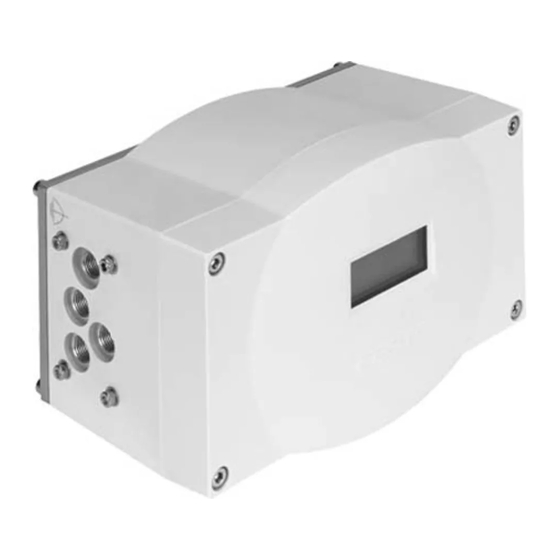
Festo CMSX-...-C-U-F1 series User Manual
Positioner
Hide thumbs
Also See for CMSX-...-C-U-F1 series:
- Operating instructions manual (8 pages) ,
- Manual (61 pages)
Table of Contents
Advertisement
Quick Links
Advertisement
Table of Contents

Subscribe to Our Youtube Channel
Related Manuals for Festo CMSX-...-C-U-F1 series


Summary of Contents for Festo CMSX-...-C-U-F1 series
- Page 1 Positioner CMSX-...-C-U-F1-... Description 8080774 2017-12b [8060617]...
- Page 2 Text designations: • Activities that may be carried out in any order 1. Activities that should be carried out in the order stated – General lists è Result of an action/References to more detailed information Festo – CMSX-...-C-U-F1-... – 2017-12b...
-
Page 3: Table Of Contents
........... . Festo – CMSX-...-C-U-F1-... – 2017-12b English... - Page 4 ............... . Festo – CMSX-...-C-U-F1-... – 2017-12b English...
-
Page 5: About This Document
Return to Festo Hazardous substances can endanger the health and safety of personnel and cause damage to the environment. To prevent hazards, the product should only be returned upon explicit request by Festo. • Consult your regional Festo contact. • Complete the declaration of contamination and attach it to the outside of the packaging. -
Page 6: Product Overview
Housing screws Base plate Blanking plug Housing Cable entry with cable fitting for electrical Pneumatic connections (G1/8) connecting cable Earth terminal Mounting thread for mounting bridge Fig. 1 CMSX-P-S-… operating elements and connections (rotary) Festo – CMSX-...-C-U-F1-... – 2017-12b English... - Page 7 Housing screws Housing Cable entry with cable fitting for external Pneumatic connections (G1/8) path/angle sensor Earth terminal Cable entry with cable fitting for electrical connecting cable Fig. 2 CMSX-P-SE-… operating elements and connections (linear) Festo – CMSX-...-C-U-F1-... – 2017-12b English...
-
Page 8: Product Variants And Type Code
Nominal flow rate 50 l/min 130 l/min Safety function Open or close in case of breakdown Block in case of breakdown Generation 1st generation 2nd generation Tab. 1 Type code CMSX – example: CMSX-P-S-C-U-F1-D-50-A Festo – CMSX-...-C-U-F1-... – 2017-12b English... -
Page 9: Safety Function
2 and 4 needed with a pneumatic emergency supply. CMSX-P-S-…-D-…-C CMSX-P-S-…-D-…-C CMSX-P-SE-…-S-…-C CMSX-P-SE-…-S-…-C Regulating effect blocking Regulating effect blocking Only valid for CMSX-…, 2. Generation Tab. 2 Overview of safety position (pneumatic initial position) Festo – CMSX-...-C-U-F1-... – 2017-12b English... -
Page 10: Cmsx-P-S
Working port (2) is pressurised. Working port (4) is exhausted. The regulating effect is opening or closing. The process valve is opened or closed, dependent on the tubing connection of the positioner to the actuator. Festo – CMSX-...-C-U-F1-... – 2017-12b English... -
Page 11: Cmsx-P-S
Safety position (pneumatic initial position) CMSX-P-S-…-D-…-C Working port (2) is blocked. Working port (4) is blocked. Compressed air is enclosed in the drive. The regulating effect is blocking. The current position of the actuator is blocked. Festo – CMSX-...-C-U-F1-... – 2017-12b English... -
Page 12: Cmsx-P-Se
Working port (2) is pressurised. Working port (4) is exhausted. The regulating effect is opening or closing. The process valve is opened or closed, dependent on the tubing connection of the positioner to the actuator. Festo – CMSX-...-C-U-F1-... – 2017-12b English... -
Page 13: Cmsx-P-Se
– Accessories è www.festo.com/catalogue. – Documents and literature è www.festo.com/sp. Service Contact your regional Festo contact person if you have technical questions è www.festo.com. Transport and storage – Store the product in a cool, dry, UV-protected and corrosion-protected environment. Ensure that storage times are kept to a minimum. -
Page 14: Mounting
è Fig. 12. 7. Secure the positioner with mounting bridge to the quarter turn actuator: – 4 mounting screws M5 3 – Tightening torque 3 Nm ± 20 % Fig. 11 Mounting CMSX-P-S-… (rotary) Festo – CMSX-...-C-U-F1-... – 2017-12b English... - Page 15 The angle position of the quarter turn actuator is detected by the shaft of the positioner. The shaft of the positioner can be freely rotated and does not have a mechanical stop. The permissible sensing range is 100°. Festo – CMSX-...-C-U-F1-... – 2017-12b English...
-
Page 16: Cmsx-P-Se
– Tightening torque 2.7 Nm ± 10 % 5. Secure the positioner with the mounting bridge to the housing (flange socket) – 4 mounting screws M6 2 – Tightening torque 3 Nm ± 20 % Fig. 13 Mounting CMSX-P-SE-… (linear) Festo – CMSX-...-C-U-F1-... – 2017-12b English... -
Page 17: Installation
In the case of single-acting actuators, only connect working port (4). Seal working port (2) with a blanking plug. – Keep the tubing short. 3. Connect the supply port (1) to the compressed air source. 4. Screw an appropriate silencer into the exhaust port (3). Festo – CMSX-...-C-U-F1-... – 2017-12b English... -
Page 18: Electrical
8. If commissioning is carried out immediately after installation, leave the cover dismounted. 9. Place the housing cover in position and tighten the 4 housing screws è Fig. 1, 3. – Observe the correct position of the seals. – Tightening torque: 1.5 Nm Festo – CMSX-...-C-U-F1-... – 2017-12b English... -
Page 19: Cmsx-P-Se
9. Do not put on the cover if commissioning is to be carried out immediately after installation dismounted. 10.Place the housing cover in position and tighten the 4 housing screws è Fig. 2, 3. – Observe the correct position of the seals. – Tightening torque: 1.5 Nm Festo – CMSX-...-C-U-F1-... – 2017-12b English... -
Page 20: Pin Allocation
External path/angle sensor Terminal strip 3 (pin 15, 16) D-IN- Digital input - Digital input D-IN+ Digital input + 1) Permits separate circuits if separate power supply units are used Tab. 3 Pin allocation Festo – CMSX-...-C-U-F1-... – 2017-12b English... - Page 21 Connection of digital outputs ALARM, D-OUT1 and D-OUT2 as PNP outputs – example To connect the digital outputs ALARM, D-OUT1 and D-OUT2 as PNP outputs, connect the minus pole of the load to pin 14. The PNP outputs are positive switching, from plus to minus. Festo – CMSX-...-C-U-F1-... – 2017-12b English...
- Page 22 To connect the digital outputs D-OUT1 and D-OUT2 as NPN outputs, connect the plus pole of the load to pin 13. The NPN outputs are negative switching, from minus to plus. Digital input D-IN è Pin 15, 16 15 16 Reference potential Fig. 18 Connection of digital input D-IN – example Festo – CMSX-...-C-U-F1-... – 2017-12b English...
-
Page 23: Commissioning
Value for the upper stroke limit: 100 % 100% Value for the lower setpoint limit or SPMIN seal-closing boundary: 0 % Value for the upper setpoint limit or SPMAX 100% seal-closing boundary: 100 % 1) Only CMSX-P-S-… (rotary) Festo – CMSX-...-C-U-F1-... – 2017-12b English... - Page 24 Support point at 0 % setpoint signal: 0 % 4 CURVE Support point at 5 % setpoint signal: 5 % … Support point at 100 % setpoint signal: 100 % 100% 1) Only CMSX-P-S-… (rotary) Tab. 4 Factory settings Festo – CMSX-...-C-U-F1-... – 2017-12b English...
-
Page 25: Menu Structure - Overview
4 = Press and hold Add for 3 seconds 5 = Press and hold Sub for 3 seconds 6 = Press and hold Set for 3 seconds Fig. 19 Menu structure – overview CMSX-P-S-… (rotary) Festo – CMSX-...-C-U-F1-... – 2017-12b English... -
Page 26: Overview Cmsx-P-Se
4 = Press and hold Add for 3 seconds 5 = Press and hold Sub for 3 seconds 6 = Press and hold Set for 3 seconds Fig. 20 Menu structure – overview CMSX-P-SE-… (linear) Festo – CMSX-...-C-U-F1-... – 2017-12b English... -
Page 27: Menu Structure - Basic Menu Level
– Valve position VP of the process valve in percent (VP = valve position) Note If the PID controller is active and no signal is present at the digital input, the new setpoint value is immediately effective – even in manual setpoint position mode. Festo – CMSX-...-C-U-F1-... – 2017-12b English... - Page 28 1) If the Sub pushbutton is pressed at 0 %, the value jumps to 100 %. If the Add pushbutton is pressed at 100 %, the value jumps to 0 %. Tab. 6 Operation in the initial position Festo – CMSX-...-C-U-F1-... – 2017-12b English...
-
Page 29: Operating Statuses
Press Add 1 Activate manual setpoint Activate automatic mode position mode Press Sub Press Set 3 Confirm selection and continue within the basic menu level Tab. 10 Operation with display of the operating mode Festo – CMSX-...-C-U-F1-... – 2017-12b English... -
Page 30: Menu Structure - Main Menu
1 Continue to the next menu Press Sub 2 Back to the previous menu Press Set 3 Open menu Hold down Set 6 Back to the basic menu level Tab. 12 Operation in the main menu Festo – CMSX-...-C-U-F1-... – 2017-12b English... -
Page 31: Menu 1 Sensor
Hold down Sub 5 Pressurise working port (4) and exhaust (2) as long as the pushbutton is pressed Hold down Set 6 Back to the main menu Tab. 14 Operation in the menu 1 SENSOR Festo – CMSX-...-C-U-F1-... – 2017-12b English... -
Page 32: Menu 2 Config
In the case of low level, travel to stop 1 lmt1-L In the case of high level, travel to stop 2 lmt2-H In the case of low level, travel to stop 2 lmt2-L Tab. 15 Menu 2 CONFIG Festo – CMSX-...-C-U-F1-... – 2017-12b English... - Page 33 Confirm selection and back to the menu 2 CONFIG Hold down Set 6 Back to the main menu Confirm selection and back to the main menu Tab. 16 Operation in the menu 2 CONFIG Festo – CMSX-...-C-U-F1-... – 2017-12b English...
- Page 34 Pneumatic output 4 of the drive completely exhausted Drive completely pressurised VP 100 % VP 100 % End position 1 limit1 limit2 End position 2 limit2 limit1 Stop 1 lmt1 lmt2 Stop 2 lmt2 lmt1 Tab. 17 Parameter OPEN Festo – CMSX-...-C-U-F1-... – 2017-12b English...
- Page 35 The parameter is effective independently of the setpoint characteristic curve type. Display Description The setpoint position is increased with a rising setpoint value (presetting) increase The setpoint position is increased with a falling setpoint value decrease Tab. 18 Parameter DIRECT Festo – CMSX-...-C-U-F1-... – 2017-12b English...
- Page 36 – Equal-percentage characteristic curve 1:50 – User-defined characteristic curve A user-defined setpoint characteristic curve can be created in the menu 4 CURVE è Chap. 9.3.4. The user-defined setpoint characteristic curve can be selected with the user-def setting. Festo – CMSX-...-C-U-F1-... – 2017-12b English...
-
Page 37: Menu 3 Para
2 Back to the previous selection Reduce value Press Set 3 Confirm selection Back to the selection Hold down Set 6 Confirm selection and back to the main menu Tab. 20 Operation in the menu 3 PARA Festo – CMSX-...-C-U-F1-... – 2017-12b English... - Page 38 – The higher the value, the weaker the setpoint specification change with the same change in speed of the deviation. – A D-part that is too high makes control more sluggish. – A D-part that is too low makes control more dynamic. Festo – CMSX-...-C-U-F1-... – 2017-12b English...
- Page 39 Display Description Value for the lower stroke limit (presetting = 0 %) MIN < MAX Value for the upper stroke limit (presetting = 100 %) MIN > MAX Tab. 21 Parameter MIN, MAX Festo – CMSX-...-C-U-F1-... – 2017-12b English...
- Page 40 If the setpoint value exceeds this value, the valve can be driven into the upper end position with the maximum control force of the actuator. Tab. 23 Parameter SPMIN, SPMAX – seal closing function Festo – CMSX-...-C-U-F1-... – 2017-12b English...
-
Page 41: Menu 4 Curve
0 … 100 %. At each support point, a setpoint position in the range of 0 … 100 % can be assigned to the setpoint value. – The user-defined setpoint characteristic curve must rise monotonically. – The user-defined setpoint characteristic curve can be selected in the menu 2 CONFIG with the CHARACTE parameter è Chap. 9.3.2. Festo – CMSX-...-C-U-F1-... – 2017-12b English... - Page 42 1) If the Sub pushbutton is pressed at 0 %, the value jumps to 100 %. If the Add pushbutton is pressed at 100 %, the value jumps to 0 %. Tab. 25 Operation in the menu 4 CURVE Festo – CMSX-...-C-U-F1-... – 2017-12b English...
-
Page 43: Menu 5 Inform
Press Add 1 Continue to the next selection Press Sub 2 Back to the previous selection Press Set 3 Back to the main menu Hold down Set Tab. 27 Operation in the menu 5 INFORM Festo – CMSX-...-C-U-F1-... – 2017-12b English... -
Page 44: Menu 6 Init
2 Back to the previous selection Press Set 3 Confirm current selection Hold down Set 6 Back to the main menu Hold down Setand Add 7 Enable function Tab. 29 Operation in the menu 6 INIT Festo – CMSX-...-C-U-F1-... – 2017-12b English... -
Page 45: Switch On Positioner
è If the current position lies outside the measuring range, an error message is displayed. *SENSOR* ERROR Mount the positioner so that the sensing range of the sensor completely covers the work space of the actuator è Chap. 7. Festo – CMSX-...-C-U-F1-... – 2017-12b English... - Page 46 6. Press the Set pushbutton to open the main menu level again. --MENU-- 1 SENSOR 7. To display the initial position again, hold down the Set pushbutton for 3 seconds. --- 0.0% VP: 0.0% Festo – CMSX-...-C-U-F1-... – 2017-12b English...
-
Page 47: Initialisation
2. Then briefly press the Sub pushbutton several times until the menu 6 INIT is displayed. --MENU-- 6 INIT 3. Press Set pushbutton. *INITIA* Autoinit 4. To start automatic initialisation, hold down the Set and Add pushbuttons simultaneously for 3 seconds. è Automatic initialisation begins. The actuator is moved. Festo – CMSX-...-C-U-F1-... – 2017-12b English... - Page 48 6. Hold down the Set pushbutton for 3 seconds to open the main menu level again. --MENU-- 6 INIT 7. To display the initial position again, hold down the Set pushbutton for 3 seconds. --- 0.0% VP: 0.0% Festo – CMSX-...-C-U-F1-... – 2017-12b English...
-
Page 49: Perform User-Guided Initialisation (Userinit)
è The step is executed. The drive is moved. The next step is displayed. UserInit 11-2 8. Start each step by pressing the Add pushbutton. è After successful completion of user-guided initialisation, the following message is displayed: UserInit Festo – CMSX-...-C-U-F1-... – 2017-12b English... -
Page 50: Set Parameters
• Observe limit values. After the supply voltage is switched on, the positioner is in the same operating status and the same operating mode as was valid before the supply voltage was switched off. Festo – CMSX-...-C-U-F1-... – 2017-12b English... -
Page 51: Maintenance
PID controller is not active Start PID controller è Chap. 9.2.2, Tab. 8. Device reacts to a signal at Change signal at the digital input the digital input or correct parameterisation è Chap. 9.3.2, Tab. 15. Festo – CMSX-...-C-U-F1-... – 2017-12b English... - Page 52 Check operating voltage supply è Technical data. position, even though outside the permissible range or another setpoint value is switched off. The solenoid valves specified take on the neutral position è Chap 3.4. Tab. 30 Fault clearance Festo – CMSX-...-C-U-F1-... – 2017-12b English...
-
Page 53: Dismantling
7. Loosen 4 mounting screws from the housing (flange socket) and remove the positioner with mounting bridge è Fig. 13, 2. Disposal • Observe the local regulations for environmentally friendly disposal. • Dispose of the product in an environmentally friendly manner. Festo – CMSX-...-C-U-F1-... – 2017-12b English... -
Page 54: Technical Data
– CMSX-…-G1 0.1 … 10 – CMSX-… (2. generation) 0.5 … 10 Operating medium Compressed air according to ISO 8573-1:2010 [7:4:4] 1) Only in combination with a mounting bridge according to accessories è www.festo.com/catalogue Festo – CMSX-...-C-U-F1-... – 2017-12b English... - Page 55 High-alloy stainless steel – Seals – Adapter plate Aluminium – Plate (back plate) Aluminium – Cable connection 1) Only in combination with a mounting bridge according to accessories è www.festo.com/catalogue Tab. 31 Technical data Festo – CMSX-...-C-U-F1-... – 2017-12b English...
-
Page 56: Index
......Input setpoint value ..... Festo – CMSX-...-C-U-F1-... – 2017-12b English... - Page 57 CMSX-...-C-U-F1-... Festo – CMSX-...-C-U-F1-... – 2017-12b English...
- Page 58 Copyright: Festo AG & Co. KG Ruiter Straße 82 73734 Esslingen Germany Phone: +49 711 347-0 Fax: +49 711 347-2144 Reproduction, distribution or sale of this document or communica E-mail: tion of its contents to others without express authorization is service_international@festo.com...
Need help?
Do you have a question about the CMSX-...-C-U-F1 series and is the answer not in the manual?
Questions and answers