Festo CMMS-ST-C8-7 Assembly And Installation Manual
Motor controller
Hide thumbs
Also See for CMMS-ST-C8-7:
- Mounting and installation (72 pages) ,
- Brief overview (86 pages)

Related Manuals for Festo CMMS-ST-C8-7


Summary of Contents for Festo CMMS-ST-C8-7
- Page 1 Motor controller Manual Assembly and installation Type CMMS-ST-C8-7 Manual 554 340 en 0903b [748 685]...
- Page 3 Edition _____________________________________________________________ en 0903b Description ______________________________________________ P.BE-CMMS-ST-HW-EN Order no. ____________________________________________________________ 554 340 (Festo AG & Co KG., D-73726 Esslingen, 2009) Internet: http://www.festo.com E-mail: service_international@festo.com The copying, distribution and utilization of this document as well as the communication of its contents to others without expressed authorization is prohibited. Offenders will be held liable for compensation of damages.
- Page 4 Index of revisions Author: Festo AG & Co. KG Name of manual: MOTORCONTROLLER CMMS-ST-C8-7 File name: File saved at: Consec. no. Description Index of revisions Date of amendment Produced: 0702NH 28.06.2007 Revision 0810a 30.10.2008 Revision - Functional safety engineering 0903b 07.09.2009...
-
Page 5: Table Of Contents
Table of contents General information ....................9 Documentation ...................... 9 Type key CMMS-ST-C8-7 ..................9 Scope of delivery ....................10 Safety instructions for electrical drives and controllers ........11 Symbols used ...................... 11 General Information .................... 12 Hazards due to improper use ................13 Safety instructions .................... - Page 6 On-the-fly measurement ..............74 3.5.17 Endless positioning ................74 3.5.18 Relative positioning records ..............75 Functional safety engineering ................76 General information and intended use ..............76 STO, Safe torque off .................... 76 SS1, Safe Stop 1 ....................79 Festo.P.BE-CMMS-ST-HW-EN 0903b...
- Page 7 General connection instructions ................ 104 Tools/material ....................104 Connecting the motor ..................104 Connect the CMMS-ST stepping motor controller to the power supply ..... 105 Connecting a PC ....................105 Checking readiness for operation ..............105 Timing diagram switch-on sequence ..............106 Festo.P.BE-CMMS-ST-HW-EN 0903b...
- Page 8 Motor connection [X6] ................ 116 A.3.3 Incremental encoder input [X2] ............117 A.3.4 Incremental sensor interface [X10] ............. 117 A.3.5 RS232/RS-485 [X5] ................118 A.3.6 CAN bus [X4] ..................118 A.3.7 I/O interface [X1] ................118 Glossary ......................120 INDEX ........................121 Festo.P.BE-CMMS-ST-HW-EN 0903b...
-
Page 9: General Information
CANopen protocol according to DSP402 PROFIBUS manual ‚ P.BE-CMMS-FHPP-PB-…‛: Description of the implemented PROFIBUS-DP protocol. DeviceNet manual ‚P.BE-CMMS-FHPP-DN-…‛: Description of the implemented DeviceNet protocol. FHPP manual ‚P.BE-CMM-FHPP-…‛: Description of the implemented Festo profiles for handling and positioning. Type key CMMS-ST-C8-7 — — —... -
Page 10: Scope Of Delivery
1. General information Scope of delivery The delivery includes: Number Delivery Stepping motor controller CMMS-ST-C8-7 CD (configuration software, documentation, S7 module, GSD, EDS, firmware) Brief description NEKM-C-1 plug assortment Tab. 1.1: Scope of delivery Festo.P.BE-CMMS-ST-HW-EN 0903b... -
Page 11: Safety Instructions For Electrical Drives And Controllers
Failure to comply can result in property damage and personal injury. Warning DANGER! Considerable property damage and personal injury can occur if these instructions are not observed. Warning Dangerous voltage! The safety instructions contain reference to dangerous voltages which may occur. Accessory Environment Festo.P.BE-CMMS-ST-HW-EN 0903b... -
Page 12: General Information
2. Safety instructions for electrical drives and controllers General Information Festo AG & Co.KG is not liable for damage caused by failure to observe the warning instructions in these operating instructions. Note Before commissioning, the Safety instructions for electrical drives and controllers must be read from page 11 and the chapter 6.5 In-... -
Page 13: Hazards Due To Improper Use
Danger of death or serious bodily injury due to electric shock! Warning DANGER! High electric voltage resulting from incorrect connection! Danger of death or bodily injury from electric shock! Warning DANGER! Surfaces of the device housing may be hot! Danger of injury! Danger of burns! Festo.P.BE-CMMS-ST-HW-EN 0903b... -
Page 14: Safety Instructions
Precautionary measures must be taken for preventing interference to switching systems, e.g. switching protective switches and relays with RC elements or diodes. You must observe the safety regulations and directives of the country in which the device is to be used. Festo.P.BE-CMMS-ST-HW-EN 0903b... - Page 15 Safety of machines – basic concepts, general guidelines EN 1050 Safety of machines – guidelines for risk evaluation EN 1037 Safety of machines – avoiding unintentional starting EN ISO 13849-1 Safety-relevant parts of controllers EN 61800-5-2 Variable-speed electric drives – functional safety requirements Festo.P.BE-CMMS-ST-HW-EN 0903b...
-
Page 16: Safety Instructions For Assembly And Maintenance
– cleaning – long periods out of use. Warning Proceed carefully with mounting. Ensure that no drilling chips, metal dust or mounting material (screws, nuts, wire cuttings) fall into the stepping motor controller during mounting work and subsequent operation. Festo.P.BE-CMMS-ST-HW-EN 0903b... -
Page 17: Protection Aganst Touching Electric Components
50 V, as this can cause an electric shock. When electric devices are operated, certain components in these devices are always under dangerous tension. Warning Dangerous voltage! High voltage! Danger of death or serious bodily injury due to electric shock! Festo.P.BE-CMMS-ST-HW-EN 0903b... - Page 18 Protect the device against being switched on again. Warning During installation note the amount of intermediate circuit voltage, especially with regard to insulation and protective measures. Make sure that the earthing, the cross section size of the conductor and the corresponding short-circuit protection are correct. Festo.P.BE-CMMS-ST-HW-EN 0903b...
-
Page 19: Protection By Low Voltage (Pelv) Against Electric Shock
Warning DANGER! Dangerous movements! Danger of injury or death, serious bodily injury or material damage. Festo.P.BE-CMMS-ST-HW-EN 0903b... -
Page 20: Protection Aganst Touching Hot Components
Protection during handling and installation Handling and assembling certain components in an unsuitable manner can cause injury under unfavourable circumstances. Warning DANGER! Danger of injury as a result of incorrect handling Bodily injury caused by squeezing, cutting, impact! Festo.P.BE-CMMS-ST-HW-EN 0903b... - Page 21 Use lifting devices and tools in a correct manner. If necessary, use suitable protective equipment (e.g. protective glasses, safety shoes, safety gloves). Do not stand under hanging loads. Wipe up spilt liquids on the floor to avoid slipping. Festo.P.BE-CMMS-ST-HW-EN 0903b...
-
Page 22: Product Description
The CMMS-ST is intended for activating hybrid stepping motors with a maximum current of up to 8 A, in particular the MTR-STand EMMS-STseries by Festo. The MTR-ST and EMMS-ST series motors without encoders are controlled in an open control circuit (open loop). - Page 23 Parameterization program "Festo Configuration Tool FCT" Simplest start-up and diagnosis Confiuration of motor controller, motor and axis Automatic adjustment of all controller parameters with use of Festo Mechanics 2-channel oscilloscope function English and German Festo.P.BE-CMMS-ST-HW-EN 0903b...
-
Page 24: Interfaces
Mode 0/1/2) Jog mode Tab. 6.2 ff Linked positioning records CANopen field bus X4 (CAN) Direct application Speed control 3.4.2 Homing run Torque control Tab. 6.7 Jog mode Positioning control Record selection Interpolated position mode (DS402) Tab. 3.2 Interfaces Festo.P.BE-CMMS-ST-HW-EN 0903b... -
Page 25: Analogue Setpoint Specification
If the motor controller works as master, it can provide (RS422) A/B signals to the incremental encoder output (X10). When the motor controller is to operate as a slave, various inputs and signal forms are available for synchronization. [5V RS422]: A/B, CW/CCW, CLK/DIR [24V]: CW/CCW, CLK/DIR Festo.P.BE-CMMS-ST-HW-EN 0903b... - Page 26 The following signals can be evaluated: A/B tracking signals CLK/DIR – pulse/direction CW/CCW pulse Input: Processing of pulse-direction signals 24 V DC (X1) CLK/DIR – pulse/direction CW/CCW pulse 24 V DC pulse-direction signals are carried out via X1 DIN2 and DIN3. Festo.P.BE-CMMS-ST-HW-EN 0903b...
- Page 27 To ensure flexibility of the controller, synchronization should be switched on over the I/O interface. Necessary I/O triggering during synchronization via FCT DIN4 Output stage enable DIN5 Controller enable DIN6 Limit switch 0 DIN7 Limit switch 1 DIN13 Stop Festo.P.BE-CMMS-ST-HW-EN 0903b...
- Page 28 Required I/O triggering during synchronization via mode switchover with 24 VDC frequency signals The connection plan shows the switch position in the active operating state. *) The limit switches are set by default to opener (configuration over FCT) Festo.P.BE-CMMS-ST-HW-EN 0903b...
- Page 29 Required I/O triggering during synchronization via mode switchover with 5 VDC frequency signals The connection plan shows the switch position in the active operating state. *) The limit switches are set by default to opener (configuration over FCT) Festo.P.BE-CMMS-ST-HW-EN 0903b...
- Page 30 The signal MC is set as long as the drive is at standstill with active synchronization (DIN8: START set). That is, the MC signal is set as long as the window for "DZ = 0 recognised" has not been left. Festo.P.BE-CMMS-ST-HW-EN 0903b...
-
Page 31: I/O Functions And Device Control
MODE switching allows you to switch between the following default settings: Mode Function Mode 0 Positioning Mode 1 Jog function Mode 2 Record linking Mode 3 Synchronization Tab. 3.4: Mode switching Festo.P.BE-CMMS-ST-HW-EN 0903b... -
Page 32: Rs232 Interface (Diagnosis/Parameterization Interface)
Tab. 3.7: Setting for terminal program Please note that, immediately after a reset, the motor controller independently issues a bootup message via the serial interface. A reception program on the controller must either process or reject these received characters. Festo.P.BE-CMMS-ST-HW-EN 0903b... - Page 33 Reading an actual value of a CO OI:nnnn nnnn:HHHHHHHH or OI:EEEEEEEE nnnn: Number of the communication object (CO), 16 bit (hexadecimal format) HHHHHHHH: 32 bit data / values (hexadecimal format) EEEEEEEE: Return value in case of an access fault Tab. 3.9: Parameter commands Festo.P.BE-CMMS-ST-HW-EN 0903b...
- Page 34 OK! or OW:EEEEEEEE Positioning OW:0030:00000002 Tab. 3.12: Operating mode Faulty return values can be called up due to invalid values that do not come from the above-named group. The current operation mode can be read by using the "OR" command. Festo.P.BE-CMMS-ST-HW-EN 0903b...
- Page 35 Tab. 3.13: Design of a null modem line Configuration in the FCT For configuration, the following settings are required in the "Work station" window: On the "Application data" page in the "Operating modes settings" tab, set the control interface to "RS-485". Festo.P.BE-CMMS-ST-HW-EN 0903b...
- Page 36 The commands of type "OW", "OR" etc. support an optional check sum. This check sum is formed without the first five characters. The bootup message of the boot loader as well as the bootup message of the firmware are sent in the RS232 mode. Festo.P.BE-CMMS-ST-HW-EN 0903b...
- Page 37 The acceleration is thereby written in "acceleration units". That means, they depend on the set CAN factor group. The default setting here is 1 / 2 revolutions/min/s. (24 bit portion before the point, 8 bit portion after the point. =608300:00138800 Acceleration 5000 RPM/s Command: Festo.P.BE-CMMS-ST-HW-EN 0903b...
- Page 38 Homing mode 8. Start homing 9. Homing is started via the CAN control word (COB 6040_00): 10. Controller enable is controlled via bit 0 ... 3. 11. The homing run is started via a rising edge at bit 4. Festo.P.BE-CMMS-ST-HW-EN 0903b...
-
Page 39: Multi-Firmware Strategy
The brake chopper is actuated with software control. The internal braking resistor is protected against overloading via software and hardware. Note If the maximum braking energy of the braking resistor is exceeded, the message "070 – Overvoltage in intermediate circuit" is output and the end stages switched off. Festo.P.BE-CMMS-ST-HW-EN 0903b... -
Page 40: 3.3.10 Control Interface X1
Limit switch 1 Limit switch 1 Limit switch 1 Limit switch 1 DIN8 Start for positioning Teach Start record Start record procedure linking synchronization DIN9 High-speed input "0" = jog mode "1" = record "1" = slave linking synchronization Festo.P.BE-CMMS-ST-HW-EN 0903b... - Page 41 Ready for operation output (high active) DOUT1 Default motion complete Speed 0 reached output (high active) DOUT2 Default start ack output Teach ack Default start ack Position (low active) synchronized DOUT3 Default error output Error Error Error Tab. 3.14: Interface assignment Festo.P.BE-CMMS-ST-HW-EN 0903b...
- Page 42 2 x pulse/direction (CLK/DIR or CW/CCW on DIN2, 3) 1 x start sync (DIN8) Tab. 3.15: Control interface X1 The digital inputs are designed to be configurable: Mode DIN9 DIN12 Function Positioning Jog mode Record linking Synchronization Tab. 3.16: Mode switching Festo.P.BE-CMMS-ST-HW-EN 0903b...
-
Page 43: Serial Parameterization Interface Rs232 And Rs-485 - X5
When a parameter set is loaded from the memory card, the newest parameter set is always loaded. Also, the parameter set can be used to specify whether firmware and/or a parameter set is to be loaded from the memory card automatically on activation. Festo.P.BE-CMMS-ST-HW-EN 0903b... -
Page 44: Field Bus Interface
But only one field bus can be active at any given time. For all field busses, the Festo Profile for Handling and Positioning (FHPP) has been implemented as the communication protocol. Additionally, for the CAN bus, the... -
Page 45: Fhpp
(process data objects). Two PDOs are available for each sending direction (transmit/receive). Contour control with linear interpolation With the "interpolated position mode", a contour control can be implemented in a multi- axis application of the controller. For this, position setpoints are specified by a higher- Festo.P.BE-CMMS-ST-HW-EN 0903b... -
Page 46: Profibus
The controller is connected to the DeviceNet network with a corresponding expansion module (CAMC-PB), which can be plugged into the expansion slot X7. If the module is plugged in, it automatically becomes active the next time the controller is switched on. Festo.P.BE-CMMS-ST-HW-EN 0903b... -
Page 47: Mtr-St Series Stepper Motors
Simple connection via digital I/Os to a higher-order control system, e.g. a PLC. Jolt-limited or time-optimised positioning absolutely or relative to a reference point via the integrated trajectory generator. Position specification via the integrated field bus CANopen with automatic interpolation between the setpoints. Festo.P.BE-CMMS-ST-HW-EN 0903b... - Page 48 Positioning Record selection controller Field bus Direct mode Field bus Record selection Reference run Record selection Field bus Direct mode Field bus Record selection Jog mode Field bus Direct mode Teach-in function via I/O Tab. 3.17: Operating modes Festo.P.BE-CMMS-ST-HW-EN 0903b...
-
Page 49: Timing Diagram Operation Mode Switchover
The speed setpoint (without the correction value) is reached via a setpoint ramp. Four acceleration ramps can be configured in the range of one controller cycle of up to approx. 10 s. The setpoint ramp can be deactivated. Festo.P.BE-CMMS-ST-HW-EN 0903b... -
Page 50: Suppression Of Ranges
The position records are made up of a position value and a motion profile. The following parameters can be set for the eight motion profiles: Positioning speed Acceleration Delay Smoothing Festo.P.BE-CMMS-ST-HW-EN 0903b... - Page 51 RS232 interface (for test purposes only) or a field bus interface. Required I/O connection for positioning The connection plan shows the switch position in the active operating state. *) The limit switches are set by default to opener (configuration over FCT) Festo.P.BE-CMMS-ST-HW-EN 0903b...
-
Page 52: Homing Run
Run to Positive Negative Graphical representation method method Dec Hex Dec Hex Limit switch with zero pulse evaluation Fixed stop with zero pulse evaluation Limit switch Fixed stop Zero pulse Save current position Tab. 3.18: Homing run methods Festo.P.BE-CMMS-ST-HW-EN 0903b... - Page 53 If configured: Run at travel speed to axis zero point. Negative stop Run at search speed in negative direction to stop. This position is saved as a reference point. If configured: Run at travel speed to axis zero point. Festo.P.BE-CMMS-ST-HW-EN 0903b...
- Page 54 If configured: Run at travel speed to axis zero point. Note: If the reference system is shifted, runs to the limit switch or fixed stop are possible. The are therefore generally used for rotating axes. Tab. 3.19: Explanation of the homing methods Festo.P.BE-CMMS-ST-HW-EN 0903b...
-
Page 55: Timing Diagrams For Homing Run
Limit switch E0 Limit switch E1 DOUT0: READY DOUT1: MC DOUT2: ACK DOUT3: ERROR – = 1.6 ms = x ms (dependent on ramps) Fig. 3.4: Signal sequence with start of the homing run and with positive design Festo.P.BE-CMMS-ST-HW-EN 0903b... - Page 56 START Limit switch E0 Limit switch E1 DOUT0: READY DOUT1: MC DOUT2: ACK DOUT3: ERROR Drive is moving = 1.6 ms = x ms (dependent on ramps) Fig. 3.5: Signal sequence with faulty interruption (contour error, ...) Festo.P.BE-CMMS-ST-HW-EN 0903b...
-
Page 57: Trajectory Generator
After a start signal is detected, positioning is cancelled and the drive runs at a constant speed. After pre-calculation is completed, the drive runs to the new target position. The trajectory generator sends the following messages: Target reached, (Default: digital output DOUT1 – MC) Remaining distance reached. Festo.P.BE-CMMS-ST-HW-EN 0903b... -
Page 58: 3.5.10 I/O Sequence Control
Speed control Position control T10 T11 Homing Jog mode Transition condition Actions of the user RESET / Power ON Time out has expired or the firmware download is complete. The initialisation has been carried out successfully. DIN4=1 and DIN5=1 Festo.P.BE-CMMS-ST-HW-EN 0903b... - Page 59 Parameter record was loaded A fault has occurred which causes the end stage to be switched off Edge controlled fault acknowledgement DIN5: 1 … 0 The error was acknowledged and no other errors are pending. Tab. 3.20: I/O sequence control Festo.P.BE-CMMS-ST-HW-EN 0903b...
-
Page 60: 3.5.11 Fault Messages
Holding brake Current-carrying Motor controlled DOUT0 : READY Drive is moving = 1.6 ms = x ms (dependent on brake ramps) = x ms (dependent on set switch-off delay) Fig. 3.7: Behaviour when controller enable is switched off Festo.P.BE-CMMS-ST-HW-EN 0903b... - Page 61 DOUT0 : READY Drive is moving = 1.6 ms = x ms (dependent on set switch-off delay) Fig. 3.8: Behaviour when end-stage enable is switched off Note The holding brake of the EMMS-ST-…-SB/-SEB is not suitable for braking the motor. Festo.P.BE-CMMS-ST-HW-EN 0903b...
-
Page 62: 3.5.13 Oscilloscope Function
If the trigger condition occurs, the measurement process is cancelled after a defined number of scan steps. The data transfer section also has low priority. It is integrated in the time slice of the serial communication. Festo.P.BE-CMMS-ST-HW-EN 0903b... -
Page 63: 3.5.14 Jog And Teach Function I/O
"Read from SD after restart" must be inactive, otherwise, when the controller is restarted, the old values will be read off the SD card again. Activating jog/teach function The jog/teach function is started in I/O operation through selection of mode 1. Festo.P.BE-CMMS-ST-HW-EN 0903b... - Page 64 3. Product description Necessary I/O connection with jog/teach The connection plan shows the switch position in the active operating state. *) The limit switches are set by default to opener (configuration over FCT) Festo.P.BE-CMMS-ST-HW-EN 0903b...
- Page 65 3. Technical specificationsProduct description Settings in the FCT The parameters set here are valid for jogging via I/O interface and jogging via FCT. The acceleration also applies with "single step" over FCT. Festo.P.BE-CMMS-ST-HW-EN 0903b...
- Page 66 START/TEACH STOP DIN11: Jog - DIN10: Jog + DOUT0: READY DOUT1: MC DOUT2: ACK-TEACH DOUT3: ERROR Drive is moving = 1.6 ms = x ms (dependent on brake ramps) Fig. 3.10: Signal sequence with jogging positive and negative Festo.P.BE-CMMS-ST-HW-EN 0903b...
- Page 67 DOUT1: MC DOUT2: ACK-TEACH DOUT3: ERROR Drive is moving – – – – + – = 1.6 ms = x ms (dependent on brake ramps) Fig. 3.11: Signal sequence when both signals are activated simultaneously / briefly staggered Festo.P.BE-CMMS-ST-HW-EN 0903b...
-
Page 68: Position Record Linking With Positioning/Torque Control Switching
7 different sequences are possible. Under FHPP, the entry is freely selectable and the number limited only by the maximum number of position records. The program lines are worked off every 1.6 ms. This ensures that a set output remains set for at least 1.6 ms. Festo.P.BE-CMMS-ST-HW-EN 0903b... - Page 69 Continues after the motion complete message and a negative edge waiting on DIN10 (NEXT1) or DIN11 (NEXT2). Tab. 3.21: Step criteria Note The time specification for STS and TIM is the time entered in the motion profile. The time b egins with execution of the position record. Festo.P.BE-CMMS-ST-HW-EN 0903b...
- Page 70 Position record profiles that contain an end speed <> 0 must NOT be used for individual records, since the drive would continue to run uncontrolled. Activation of record linking Record linking is started in I/O operation through selection of mode 2. Festo.P.BE-CMMS-ST-HW-EN 0903b...
- Page 71 With removal of DIN9 "Mode switchover", the ongoing record linking is ended. The ongoing position record is still run to the end. With removal of DIN13 "Stop", record linking is interrupted. Record linking must then be initialized again. Festo.P.BE-CMMS-ST-HW-EN 0903b...
- Page 72 DOUT0: READY DOUT1: MC DOUT2: ACK DOUT3: ERROR Drive is moving = 1.6 ms = x ms (dependent on positioning) Applies for positioning records with end speed = 0 Fig. 3.13: Signal sequence at the start of a sequence Festo.P.BE-CMMS-ST-HW-EN 0903b...
- Page 73 ENABLE START STOP HALT Positioning record DOUT0: READY DOUT1: MC DOUT2: ACK DOUT3: ERROR Drive is moving = 1.6 ms = x ms (dependent on brake ramps) Fig. 3.15: Signal sequence with interruption and continuation through HALT input Festo.P.BE-CMMS-ST-HW-EN 0903b...
-
Page 74: 3.5.16 On-The-Fly Measurement
For relative position records, an overrun of the position counter is possible. That is, the position counter jumps from +32767 revolutions to -32768 revolutions, for example. To be able to use the Endless Positioning function, the following settings must be made during configuration. Festo.P.BE-CMMS-ST-HW-EN 0903b... -
Page 75: 3.5.18 Relative Positioning Records
For positioning records that do not have a whole number as the result, the controller rounds up to the next whole number. This can result in deviations with endless positioning. Example: rotary indexing table 4 positions. (90°) 65536:4= 16384 ----> Integer 6 positions. (60°) 65536:6= 10922,666 ----> The controller positions at 10923. Festo.P.BE-CMMS-ST-HW-EN 0903b... -
Page 76: Functional Safety Engineering
If you use motors with a holding brake, each STO disconnection places wear and tear on the brake. Therefore, use motors without holding brakes for STO. Application examples for the STO function are manual actions during setup, changeover Festo.P.BE-CMMS-ST-HW-EN 0903b... - Page 77 If external forces (e.g. hanging loads) have an effect on the drive, additional measures (e.g. mechanical brakes) are necessary to avoid hazards. The Safe Stop 1 stop function (SS1), in which the drive is brought to standstill in a controlled manner, is then always preferred. Festo.P.BE-CMMS-ST-HW-EN 0903b...
- Page 78 4. Functional safety engineering Circuitry example Festo.P.BE-CMMS-ST-HW-EN 0903b...
-
Page 79: Ss1, Safe Stop 1
In the function "Safe Stop 1" (SS1), the drive is run down in a controlled way and, after that, the power supply to the final output stage is switched off. As a result, the drive cannot generate torque or any force at standstill and so cannot make any dangerous movements. Festo.P.BE-CMMS-ST-HW-EN 0903b... - Page 80 The switch-off delay of the holding brake must be set in the FCT. The set time is necessary, as the brake does not close immediately due to the mechanical design. If this set time = 0 or <= 10 ms, the vertically hanging load can briefly slip through. Parameterisation example FCT Circuitry example Festo.P.BE-CMMS-ST-HW-EN 0903b...
- Page 81 4. Technical specificationsFunctional safety engineering Determination of the brake time The brake time can easily be determined through the FCT Trace function. The brake time Festo.P.BE-CMMS-ST-HW-EN 0903b...
- Page 82 FCT PlugIn Version V1.1 The maximum time until the drive stands still after controller enable at speed = 0 can be set via the ‚maximum switch off delay‛ from 2 … 10000 ms. A possible measurement curve could look as follows. Festo.P.BE-CMMS-ST-HW-EN 0903b...
- Page 83 K2 and K3 also falls off. As a result, there is a two-channel switch-off. Note The ramp function of the motor controller’s Quick Stop delay is not monitored. The unintended opening of the protective door must be prevented in the system. Festo.P.BE-CMMS-ST-HW-EN 0903b...
- Page 84 For each on-off cycle of the machine, the PILZ device PNOZ XV2P checks whether the relays of the safety equipment open and close properly. The function of switching off the end stage enable and controller enable must be checked regularly (e.g. monthly) via the PLC. Festo.P.BE-CMMS-ST-HW-EN 0903b...
-
Page 85: Mechanical Installation
[X9] leading upwards Mount with the clip to the control cabinet plate Mounting clearance: For sufficient ventilation, 100 mm of clearance to other assemblies is required above and below the device. Pay attention to the fastening interval of 69 mm! Festo.P.BE-CMMS-ST-HW-EN 0903b... - Page 86 5. Mechanical installation Fig. 5.1: CMMS-ST stepping motor controller: Installation clearance Festo.P.BE-CMMS-ST-HW-EN 0903b...
-
Page 87: Assembly
The clips are part of the radiator profile, ensuring an optimal heat transfer to the control cabinet plate. Use size M4 screws to attach the CMMS-ST stepping motor controller. Fig. 5.2: CMMS-ST stepping motor controller: Assembly Festo.P.BE-CMMS-ST-HW-EN 0903b... -
Page 88: Electrical Installation
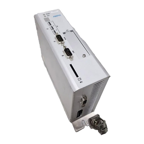
6. Electrical installation Electrical installation Device view 1 Status display 2 S1: Field bus settings and boot loader 3 Technology module (optional) 4 M1: SD memory card 5 X4: CAN bus 6 X5: RS232/485 Fig. 6.1: CMMS-ST view Front Festo.P.BE-CMMS-ST-HW-EN 0903b... - Page 89 6. Technical specificationsElectrical installation 1 Earthing bolt 2 X9 power supply 3 X10 Incremental encoder interface 4 X1 I/O interface Fig. 6.2: CMMS-ST top view Festo.P.BE-CMMS-ST-HW-EN 0903b...
-
Page 90: Interfaces
If the polarity of the operating voltage connections is reversed, or if the operating voltage is too high or the operating voltage and motor connections are incorrectly connected, the CMMS-ST stepping motor controller will be damaged. Festo.P.BE-CMMS-ST-HW-EN 0903b... -
Page 91: Cmms-St Complete System
Power pack for the control voltage Power pack for the power supply Stepper motor controller CMMS-ST Motor with motor cable Increment generator cable (for motors with increment generators) A PC with a serial connection cable is required for parameterizing. Festo.P.BE-CMMS-ST-HW-EN 0903b... - Page 92 6. Electrical installation 1 Main switch 2 Fuse 3 Power pack for control voltage 4 Power pack for power supply 5 CMMS-ST 6 PC 7 Motor Fig. 6.4 Complete structure of CMMS-ST with motor and PC Festo.P.BE-CMMS-ST-HW-EN 0903b...
-
Page 93: Interfaces
+24 V 24 V 100 mA 24 V feed-in feed-out DIN0 Record selection 0 (high active) DIN2 Record selection 2 (high active) DIN4 End stage enable (high active) DIN6 Limit switch 0 DIN8 Start for the positioning procedure Festo.P.BE-CMMS-ST-HW-EN 0903b... - Page 94 End stage enable (high active) DIN6 Limit switch 0 DIN8 Teach (high active) DOUT0 24 V 100 mA Ready for operation output (high active) DOUT2 24 V 100 mA Teach ack Tab. 6.3: Pin allocation: I/O interface [X1] Mode 1 Festo.P.BE-CMMS-ST-HW-EN 0903b...
- Page 95 DIN8 Start record linking DOUT0 24 V 100 mA Ready for operation output (high active) DOUT2 24 V 100 mA Output freely programmable - default start ack (high active) Tab. 6.4: Pin allocation: I/O interface [X1] Mode 2 Festo.P.BE-CMMS-ST-HW-EN 0903b...
- Page 96 End stage enable (high active) DIN6 Limit switch 0 DIN8 Start synchronization DOUT0 24 V 100 mA Ready for operation output (high active) DOUT2 24 V 100 mA Setpoint reached output (high active) Tab. 6.5: Pin allocation: I/O interface [X1] Mode 3 Festo.P.BE-CMMS-ST-HW-EN 0903b...
-
Page 97: Incremental Encoder Input [X2]
Connection for the cable screen – CAN-GND, electrically connected to GND in the controller CANH 5 V, Ri = 60 Ohm CAN-high signal line – – – – – – Tab. 6.7: Pin allocation: Field bus CAN [X4] Festo.P.BE-CMMS-ST-HW-EN 0903b... -
Page 98: Rs232/Rs-485 [X5]
String A/ – String B – String B/ – – Motor temperature sensor, either N/C contact or PTC (in preparation) – – Motor holding brake – Tab. 6.10: Pin allocation: Motor connection [X6] Festo.P.BE-CMMS-ST-HW-EN 0903b... -
Page 99: Power Supply [X9]
Anticlockwise cycles CCW Negative polarity as per RS422 Incremental encoder zero pulse N 5 V, Ri = 120 Ohm Negative polarity acc. to RS422 – Screen for the connecting cable Tab. 6.13: Pin allocation: Incremental encoder output/pulse, direction input [X10] Festo.P.BE-CMMS-ST-HW-EN 0903b... -
Page 100: Sd Card
(If the switch is set to ON, the system searches for new firmware on the SD card) Baud rate Activation of the CAN interface Terminating resistor Tab. 6.14: Assignment of the DIP switches DIP switches ON/OFF Meaning DIP switch 1 is the lowest bit. 1011011 = 91 Tab. 6.15: Sample node number Festo.P.BE-CMMS-ST-HW-EN 0903b... -
Page 101: Instructions On Safe And Emc-Compliant Installation
In order to increase the interference immunity and decrease the interference emission, the CMMS-ST already has integrated motor throttles and mains filters, which means that the CMMS-ST stepping motor controller can be operated without additional screens and filters in most applications. Festo.P.BE-CMMS-ST-HW-EN 0903b... -
Page 102: Emc Areas: Second Environment
5. Unscreened signal and control lines should not be used. If they must be used, they should at least be twisted. 6. Even screened lines always have short unscreened parts at either end (unless a screened plug housing is used). Festo.P.BE-CMMS-ST-HW-EN 0903b... -
Page 103: Operation With Long Motor Cables
If non-assigned plug connectors are used, there is a danger that damage may occur to the device or to other parts of the system as a result of ESD (electrostatic discharge). Protective caps are available from specialised retailers to prevent such discharges. Festo.P.BE-CMMS-ST-HW-EN 0903b... -
Page 104: Preparations For Commissioning
3. Insert the motor cable plug in the corresponding socket on the motor and secure it. 4. Insert the D-sub plug in socket [X2] of the device and secure the locking screws. 5. Check all plug connectors once again. Festo.P.BE-CMMS-ST-HW-EN 0903b... -
Page 105: Connect The Cmms-St Stepping Motor Controller To The Power Supply
1. Switch off the supply voltage. lights up 2. Wait for one minute to allow the intermediate circuit to discharge. 3. Check all connecting cables. 4. Check that the 24 V control voltage is functional. 5. Switch on the supply voltage again. Festo.P.BE-CMMS-ST-HW-EN 0903b... -
Page 106: Timing Diagram Switch-On Sequence
Depends on the operating mode and the state of the drive = N x 1.6 ms Can be parameterized (brake parameter run start delay tF) = ca. 300 ms Time for determination of commutator position Fig. 7.1: Timing diagram switch-on sequence Festo.P.BE-CMMS-ST-HW-EN 0903b... -
Page 107: Service Functions And Error Messages
The heat sink temperature of the power output stage is measured with a linear temperature sensor. Temperature monitoring is triggered at temperatures below – 40 °C and above 85 °C. A temperature warning is issued at 80 °C. Festo.P.BE-CMMS-ST-HW-EN 0903b... -
Page 108: I²T Monitoring
8.1.7 Commissioning status Stepping motor controllers sent to Festo for servicing have other firmware and parameters loaded for testing purposes. The CMMS-ST must be configured before it is commissioned again at the customer's premises. The configuration software queries the commissioning status and prompts the user to configure the stepping motor controller. -
Page 109: Error Messages
The fault cannot be rectified automatically. PS off Send stepping motor controller to your local 24 V supply fault sales partner. 12 V supply fault Short circuit in end stage Motor defective? PS off Short-circuit in cable? End stage defective? Festo.P.BE-CMMS-ST-HW-EN 0903b... - Page 110 Technology module defective? PS off Faulty initialization Please contact technical support. PROFIBUS Check set slave address PS off communication fault Check bus connection Check cables Checksum fault Error cannot be rectified independently. PS off Please contact Technical Support. Festo.P.BE-CMMS-ST-HW-EN 0903b...
- Page 111 Check the parameterization of the affected positioning records. Positioning: Acceleration too low for v_max. PS off Position data record error Limit switch negative Warn Limit switch positive Limit switches: Check parameters, wiring and limit switches. Both active Festo.P.BE-CMMS-ST-HW-EN 0903b...
- Page 112 PS off: Switch off power section Qstop: Fast stop Warn: Warning Ignore: Ignore Tab. 8.2: Error messages Error messages can be acknowledged with: the parameterizing interface, via the field bus (control word), a falling edge at DIN5 (controller enable). Festo.P.BE-CMMS-ST-HW-EN 0903b...
- Page 113 8. Technical specificationsService functions and error messages Note Starting with Firmware 1.3.0.1.7, errors that are parameterized as warnings are automatically acknowledged if the cause is no longer present. Festo.P.BE-CMMS-ST-HW-EN 0903b...
-
Page 114: Technical Specifications
Characteristics Values Device dimensions (H*W*D) 160x50x160 mm Weights 2.0 kg Tab. A.2: Technical data: Dimensions and weight Key features Values Current regulator 20 µs Speed regulator 200 µs Position Control 400 µs Tab. A.3: Technical data: Cycle times Festo.P.BE-CMMS-ST-HW-EN 0903b... -
Page 115: Operation And Display Components
Element Function Seven-segment display Displays the operating mode and an error code should an error occur Ready LED (green) Ready status BUS LED (yellow) CAN bus status display Tab. A.6: Display elements Festo.P.BE-CMMS-ST-HW-EN 0903b... -
Page 116: Interfaces
Tab. A.8: Technical data: Internal braking resistor [X9] A.3.2 Motor connection [X6] Output data Values Output current Max. output current for 2 x 12 A Max. output frequency 50 kHz Tab. A.9: Technical data: Motor connection data [X6] Festo.P.BE-CMMS-ST-HW-EN 0903b... -
Page 117: Incremental Encoder Input [X2]
Values Operating modes A/B or CLK/DIR input signals A, B, N output signals Angle resolution / number of lines 32 ... 2048 Tracking signals According to RS422 standard Output impedance 120 Ω Tab. A.12: Incremental encoder interface X10 Festo.P.BE-CMMS-ST-HW-EN 0903b... -
Page 118: Rs232/Rs-485 [X5]
Tab. A.15: Technical data: Digital inputs Digital outputs Values Signal level 24 V (from logic supply) Output current <= 100 mA Number Output reaction time < 2 ms Protective function Polarity reversal, short circuit, inductive load Tab. A.16: Technical data: Digital outputs Festo.P.BE-CMMS-ST-HW-EN 0903b... - Page 119 ±10 V input section, 12 bit, differential, AIN0 < 250 µs delay time Analogue outputs: ±10 V output range, 9 bit resolution, f > 1kHz limit AOUT0 and AOUT1 Tab. A.19: Technical data: Analogue inputs and outputs [X1] Festo.P.BE-CMMS-ST-HW-EN 0903b...
-
Page 120: Glossary
Interference Sufficiently low interference emission of electrical, magnetic or emission electromagnetic interference of an electrical system or an electrical device on other devices in the environment via lines and space. Festo.P.BE-CMMS-ST-HW-EN 0903b... -
Page 121: Index
FCT ............22 FHPP Documentation ........9 Limit switch ......... 31 Field bus control I/O connection ........44 Mode ........40, 42, 93 Firmware download ......44 MTR-ST ..........22 Frequency ranges ........ 50 Frequency signals Normal operation Festo.P.BE-CMMS-ST-HW-EN 0903b... - Page 122 ........55 Documentation ........9 jog / teach ........66 record linking ........72 switching off of enable ..... 60 Record linking switch-on sequence ......106 I/O connection ........71 synchronization ........ 30 timing ..........72 Resonance ........... 50 Festo.P.BE-CMMS-ST-HW-EN 0903b...
Need help?
Do you have a question about the CMMS-ST-C8-7 and is the answer not in the manual?
Questions and answers