Table of Contents
Advertisement
Quick Links
Advertisement
Table of Contents

Related Manuals for Harman Kardon MAS 101


Summary of Contents for Harman Kardon MAS 101
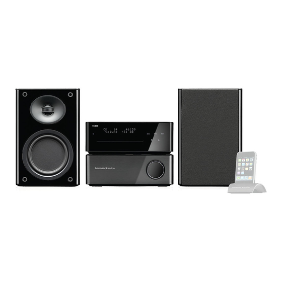
- Page 1 MAS 101/102/111 Music system Service Manual...
- Page 2 CONTENTS 1. Specification ………………………………………………………………………………………………………….….1 2. Packing …………………………………………………………………………………………………………..………3 3. Front panel information ………………………………………………………………………………………………...4 4. Rear panel information …………………………………………………………………………………………………5 5. Remote control information ……………………………………………………………………………………………6 6. Wiring diagrams ………………………………………………………………………………………………………...8 7. IC spec ……………………………………………………………………………………………………………..……9 8. Printed circuit boards ……………………………………………………………………………………………..…..41 9. Schematic diagram ………………………………………………………………………………………………..….48 10. Exploded view …………………………………………………………………………………………………………52 11.
-
Page 3: Specifications
MAS SySteM Specifications System Power output 65 watts per channel, 20hz – 20khz, thd <0.07%, into 6 ohms, both channels driven Bandwidth 20hz – 35khz, –3dB System frequency response 20hz – 20khz, ±0.5dB Signal-to-noise ratio, a-weighted 90dB (analog inputs), 96dB (digital inputs) channel separation ≥65dB crosstalk between sources... - Page 4 Signal-to-noise ratio “a” Wtg >96dBr; 22khz filter > 94dBr General Power requirement ac 230V/50hz (MaS 101/MaS 111); ac 120V/60hz (MaS 102) Power consumption <1W full standby (clock not activated); <2W standby (clock activated); 150W maximum (both channels driven) operating temperature 0°c to 40°c...
- Page 6 Front-Panel Controls MAS SySteM Controller and Amplifier note: controls are the same for all models. the MaS systems use touch-sensitive controls. to use a control, tap gently on its lit icon. USB Port A: connect a compatible uSB device here to enjoy playback of audio MP3 or WMa files.
- Page 7 AC Power Input: after you have made all other connections, plug the ac power cord into this receptacle and into an unswitched wall outlet. NOTE: MAS 101/111 systems require 23OV, 50/60Hz AC current. MAS 102 systems require 120V, 60HZ AC current.
-
Page 8: Remote Control Functions
MAS SySteM Remote control functions Power Sleep Source Selectors display Settings Info Back time navigation enter Program/Memory clear check random eject fM Mode auto Store transport controls Preset/folder +/– Volume +/– Mute numeric keys –10 numeric Key +10 numeric Key •... - Page 9 MAS SySteM Remote control functions Clear: clears the current preset station or a playlist entry. • Radio : to delete the current preset station, press the clear button while it is playing. • Playlist : While programming a playlist, press the clear button to delete the track just entered.
-
Page 10: Wiring Diagram
WIRING DIAGRAM... - Page 11 DMP3020LSS SINGLE P-CHANNEL ENHANCEMENT MODE FIELD EFFECT TRANSISTOR Please click here to visit our online spice models database. Features Mechanical Data • Low On-Resistance • Case: SOP-8L • 14mΩ @ V = -10V • Case Material: Molded Plastic, “Green” Molding Compound. UL Flammability Classification Rating 94V-0 •...
- Page 12 DMP3020LSS 3.0V 4.0V 2.5V T = 150°C = 1 2 5°C T = 85°C T = 25°C T = -55°C 2.0V 1.5V , GATE-SOURCE VOLTAGE (V) -V , DRAIN-SOURCE VOLTAGE (V) Fig. 2 Typical Transfer Characteristic Fig. 1 Typical Output Characteristic 0.03 0.03 = 1 5 0°C...
-
Page 13: Marking Information
DMP3020LSS = 2 5 °C I = -250µA -50 -25 125 150 -V , SOURCE-DRAIN VOLTAGE (V) T , AMBIENT TEMPERATURE (°C) Fig. 8 Diode Forward Voltage vs. Current D = 0.7 D = 0.5 D = 0.3 D = 0.1 D = 0.9 D = 0.05 (t) = r(t) * R... -
Page 14: Package Outline Dimensions
DMP3020LSS Package Outline Dimensions SOP-8L 1.75 ⎯ 0.08 0.25 1.30 1.50 GAUGE PLANE 0.20 Typ. SEATING PLANE 4.80 5.30 DETAIL A 5.79 6.20 3.70 4.10 7°~9° 1.27 Typ. 45° 0.35 ⎯ DETAIL A 0.38 1.27 0° 8° θ All Dimensions in mm Suggested Pad Layout Dimensions Value (in mm) -
Page 15: Related Application Notes
April 2006 FAN7602 Green Current Mode PWM Controller Features Description Green Current Mode PWM Control The FAN7602 is a green current mode PWM controller. It is specially designed for off-line adapter application, Fixed 65kHz Operation with Frequency Modulation DVDP, VCR, LCD monitor application, and auxiliary Internal High-Voltage Start-up Switch power supplies. -
Page 16: Typical Application Diagram
Typical Application Diagram FA N 7602 Figure 1. Typical Flyback Application Internal Block Diagram Vstr LUVP LUVP Auto Restart SS End Protection 2V/1.5V Latch Reset Latch Protection Circuit 5V Ref 12V/8V UVLO SS End 10ms Soft Start Driver Circuit Plimit 65kHz Clock Block Offset... -
Page 17: Pin Assignments
Pin Assignments Vstr F A N 7 6 0 2 Y W W LUVP Latch/ CS/FB Plimit Figure 3. Pin Configuration (Top View) Pin Definitions Pin Number Pin Name Pin Function Description LUVP Line Under Voltage Protection Pin. This pin is used to protect the set when the input voltage is lower than the rated input voltage range. - Page 18 April 2009 FSFR-Series — Fairchild Power Switch (FPS™) for Half-Bridge Resonant Converters Features Description The FSFR-series are a highly integrated power switches Variable Frequency Control with 50% Duty Cycle designed high-efficiency half-bridge resonant for Half-Bridge Resonant Converter Topology converters. Offering everything necessary to build a High Efficiency through Zero Voltage Switching (ZVS) reliable and robust resonant converter, the FSFR-series Internal SuperFET™s with Fast-Recovery Type...
-
Page 19: Application Circuit Diagram
Application Circuit Diagram LVcc Control KA431 sense Figure 1. Typical Application Circuit (LLC Resonant Half-Bridge Converter) Block Diagram μ 1.5 s Figure 2. Internal Block Diagram © 2007 Fairchild Semiconductor Corporation www.fairchildsemi.com FSFR series • Rev.1.0.5... - Page 20 Pin Configuration 3 4 5 6 7 8 LVcc HVcc Figure 3. Package Diagram Pin Definitions Pin # Name Description This is the drain of the high-side MOSFET, typically connected to the input DC link voltage. This pin is for enable/disable and protection. When the voltage of this pin is above 0.6V, the IC operation is enabled.
-
Page 21: Product Summary
September 2007 IRS2092 PROTECTED DIGITAL AUDIO AMPLIFIER Features Product Summary • Integrated analog input Class D audio amplifier driver in a small 16 pin package ± 100 V (max) • Floating inputs enable easy half bridge OFFSET 1.0 A implementation Gate driver •... -
Page 24: Typical Application
Product Specification SG6961 Power Factor Controller FEATURES DESCRIPTION Boundary Mode PFC Controller The SG6961 is an 8-pin boundary mode PFC controller IC Low Input Current THD intended for controlling PFC pre-regulators. The SG6961 Controlled On-Time PWM provides a controlled on-time to regulate the output DC Zero-Current Detection voltage and achieve natural power factor correction. -
Page 25: Pin Configuration
Product Specification SG6961 Power Factor Controller MARKING DIAGRAMS PIN CONFIGURATION T: D=DIP, S=SOP Z=Lead Free + ROHS Compatible SG6961TP Null=regular package COMP XXXXXXXX: Wafer Lot XXXXXXXXYWWV Y: Year; WW: Week V: Assembly Location ORDERING INFORMATION Part Number Pb-Free Package SG6961SZ 8-Pin SOP SG6961DZ 8-Pin DIP... - Page 26 Product Brief ADJUSTABLE PRECISION SHUNT REGULATORS AZ431-A Description Parametric Table The AZ431-A series ICs are three-terminal adjustable AZ431A-A AZ431B-A shunt regulators with guaranteed thermal stability over a (Max) (mA) full operation range. These ICs feature sharp turn-on char- acteristics, low temperature coefficient and low output (Min) (mA) impedance, which make them ideal substitutes for Zener diodes in applications such as switching power supply,...
- Page 27 TL071, TL071A, TL071B, TL072 TL072A, TL072B, TL074, TL074A, TL074B LOW-NOISE JFET-INPUT OPERATIONAL AMPLIFIERS SLOS080D – SEPTEMBER 1978 – REVISED AUGUST 1996 Low Power Consumption Low Noise = 18 nV/ Hz Typ at f = 1 kHz Wide Common-Mode and Differential Voltage Ranges High Input Impedance .
- Page 31 February 2007 UniFET FDP20N50 / FDPF20N50 500V N-Channel MOSFET Features Description • 20A, 500V, R = 0.23Ω @V = 10 V These N- Channel enhancement mode power field ef fect DS(on) transistors are p roduced using Fairchild’ s pr oprietary, pla nar •...
-
Page 32: Absolute Maximum Ratings
QFET FQP7N80C/FQPF7N80C 800V N-Channel MOSFET General Description Features These N-Channel enhancement mode power field effect • 6.6A, 800V, R = 1.9Ω @V = 10 V DS(on) transistors are produced using Fairchild’s proprietary, • Low gate charge ( typical 27 nC) planar stripe, DMOS technology. - Page 33 PD - 97249A DIGITAL AUDIO MOSFET IRFI4212H-117P Key Parameters g Features Ÿ Integrated half-bridge package Ÿ Reduces the part count by half typ. @ 10V DS(ON) Ÿ Facilitates better PCB layout typ. Ÿ Key parameters optimized for Class-D typ. audio amplifier applications Ω...
- Page 34 April 2003 ISL9R1560PF2 15A, 600V Stealth™ Diode General Description Features • Soft Recovery ..... . t > 1.2 The ISL9R1560PF2 is a Stealth™ diode optimized for •...
-
Page 35: Electrical Characteristics
MMBT5401 PNP General Purpose Amplifier • This device is designed as a general purpose amplifier and switch for applications requiring high voltage. SOT-23 Mark: 2L PNP Epitaxial Silicon Transistor Absolute Maximum Ratings* =25°C unless otherwise noted Symbol Parameter Value Units Collector-Emitter Voltage -150 Collector-Base Voltage... - Page 36 June 2009 2N5551 / MMBT5551 NPN General Purpose Amplifier Features • This device is designed for general purpose high voltage amplifiers and gas discharge display drivers. • Suffix “-C” means Center Collector in 2N5551 (1. Emitter 2. Collector 3. Base) •...
-
Page 37: Maximum Ratings
MUR1610CT, MUR1615CT, MUR1620CT, MUR1640CT, MUR1660CT SWITCHMODE Power Rectifiers http://onsemi.com . . . designed for use in switching power supplies, inverters and as free wheeling diodes, these state–of–the–art devices have the ULTRAFAST following features: RECTIFIERS Ultrafast 35 and 60 Nanosecond Recovery Times 8.0 AMPERES 175 C Operating Junction Temperature Popular TO–220 Package... - Page 38 MUR1620CTR, MURB1620CTR Preferred Device SWITCHMODE] Power Rectifier These state−of−the−art devices are designed for use in negative switching power supplies, inverters and as free wheeling diodes. Also, http://onsemi.com used in conjunction with common cathode dual Ultrafast Rectifiers, makes a single phase full−wave bridge. ULTRAFAST RECTIFIER Features 16 AMPERES, 200 VOLTS...
- Page 41 TIP31 Series(TIP31/31A/31B/31C) Medium Power Linear Switching Applications • Complementary to TIP32/32A/32B/32C TO-220 1.Base 2.Collector 3.Emitter NPN Epitaxial Silicon Transistor Absolute Maximum Ratings =25°C unless otherwise noted Symbol Parameter Value Units Collector-Base Voltage : TIP31 : TIP31A : TIP31B : TIP31C Collector-Emitter Voltage : TIP31 : TIP31A : TIP31B...
- Page 42 TIP32 Series(TIP32/32A/32B/32C) Medium Power Linear Switching Applications • Complement to TIP31/31A/31B/31C TO-220 1.Base 2.Collector 3.Emitter PNP Epitaxial Silicon Transistor Absolute Maximum Ratings =25°C unless otherwise noted Symbol Parameter Value Units Collector-Base Voltage : TIP32 - 40 : TIP32A - 60 : TIP32B - 80 : TIP32C...
- Page 43 AMP PCB 1/2...
- Page 44 AMP PCB 2/2...
- Page 45 POWER PCB 1/2...
- Page 46 POWER PCB 2/2...
- Page 47 LED & VOL PCB / FUSE PCB...
- Page 48 SPEAKER JOINT PCB (1/2)
- Page 49 SPEAKER JOINT PCB(2/2)
- Page 50 AMP SCH...
- Page 51 POWER SCH...
- Page 52 LED & VOL SCH / FUSE SCH LED & VOL 220R 220R 220R R122ECA-D1-19.5F-24-W 220R LED5 VOL_A LED2 LED3 LED4 VOL_B DGND 4P(2.0) SO-222-S-0R-R3(D) 10D471K 0.1U/275VAC(X2) 3P(3.96) T5AL 250V...
- Page 53 SPEAKER JIONT SCH...
-
Page 55: Sub Panel
Explode List MAS AMP AMP Explode Explode Explode List List List PART.NO PART.NO PART.NO PART.NO DESCRIPTION DESCRIPTION DESCRIPTION DESCRIPTION 7448 1020 0000 VOLUME KNOB LENS 6950 102A 0000 LOCK SHEET 7548 101C 0000 VOLUME PASTEM 7648 1010 0000 VOLUME KNOB COVER 7550 1020 0000 VOLUME KNOB BRACKET 7550 501A 0000... - Page 56 AMP.Bom P/N: 0082-1003-0000 Qty Part Type Ref. Designator Part Number IRS2092SPBF ( IRF ) Protected Digital Audio amplifier IC2 IC3 1002 0920 3038 TL071IDR ( TI ) Low Noise OP Amp IC1 IC4 1002 0920 3038 2SC2235 - TRANSISTOR 1132 2350 0162 IRFI4212H-117P ( IRF ) Digital Audio Mosfet Q6 Q7 1194 2120 1630...
- Page 57 220R/1W - RES, CARBON 2413 0322 2112 330R/1W - RES, CARBON 2413 0523 3112 2.2K/1W - RES, CARBON R33 R34 2413 0522 2212 C57 C58 C59 C60 C61 C62 2103 5390 0130 47P(NPO) C38 C47 2103 5470 0130 C63 C64 2103 5470 0130 0.1uF C2 C3 C5 C8 C9 C36 C37 C41 C42 C43 C46...
- Page 58 15UH/2A L3 L4 L5 1702 0155 0000 50UH/3A L1 L2 1703 0500 0000 BCK-03(8048)D 1709 8048 0000 BCK-03(8049) 1709 8049 0000 BCK-03(8050)A 1709 8050 0000 SG08210(B) 1891 0700 0001 2P7.92 3101 6030 0200 6P2.5 3100 4060 0250 9P(2.5) 3100 5090 0200 150Ω1/8W ±5% - RES, CARBON 2401 0221 5111 390Ω1/8W ±5% - RES, CARBON...
- Page 59 15K - RES, CHIP R39 R72 2401 0821 5304 27K - RES, CHIP 2401 0822 7304 180K - RES, CHIP 2401 0821 8404 200K - RES, CHIP 2401 0822 0404 470K - RES, CHIP R42 R43 R44 R45 R46 2401 0824 7404 470K1%-1206 - RES, CHIP R61 R62 R63 R64 2401 0914 7405...
- Page 60 LED.Bom P/N: 0082-1191-0000 Qty Part Type Ref. Designator Part Number IL0445W31BOLG201(white)H5mm LED2 LED3 LED4 LED5 1402 0705 0006 R122ECA-D1-19.5F-24-W 4401 2211 9524 4P(2.0) JEDEC 3100 4040 0200 220R±5% R17 R18 R63 R64 2401 0222 2111 0.1uF/50V±5% 2115 6104 0113 FUSE.Bom P/N: 0082-1101-0000 Qty Part Type Ref.