
Related Manuals for Stanley HP TWIN 8


Summary of Contents for Stanley HP TWIN 8
-
Page 1: User Manual
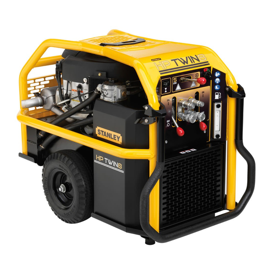
HYDRAULIC POWER UNIT USER MANUAL Safety, Operation and Maintenance © 2017 STANLEY Black & Decker, Inc. New Britain, CT 06053 U.S.A. 72464 2/2018 Ver. 14... - Page 2 2 ► HP TWIN8 User Manual...
-
Page 3: Table Of Contents
REPAIRS AND / OR SERVICE TO THIS TOOL MUST ONLY BE DONE BY AN AUTHORIZED AND CERTIFIED DEALER. For the nearest certified dealer, call STANLEY Infrastructure at (503) 659-5660 and ask for a Customer Service Representative. HP TWIN8 User Manual ◄ 3... -
Page 4: Safety Symbols
SAFETY SYMBOLS Safety symbols and signal words, as shown below, are used to emphasize all operator, maintenance and repair actions which, if not strictly followed, could result in a life-threatening situation, bodily injury or damage to equipment. This is the safety alert symbol. It is used to alert you to potential personal injury hazards. -
Page 5: Safety Precautions
SAFETY PRECAUTIONS Tool operators and maintenance personnel must always be fatal. comply with the safety precautions given in this manual • Do not operate a damaged or improperly adjusted and on the stickers and tags attached to the tool and power unit. - Page 6 SAFETY PRECAUTIONS if affected by medications, drugs or alcohol. • Keep clear of hot engine parts and exhaust. • Do not operate tools if oil temperature exceeds 140 °F/60 °C. Operation at high temperatures can cause operator discomfort or injury. •...
-
Page 7: Tool Stickers
TOOL STICKERS LOGO, TWIN8 DECAL P/N-74771 DASH, TWIN8, DECAL P/N-205043 STANLEY, HYD TANK, DECAL P/N-74770 STANLEY, FUEL TANK DECAL P/N-74706 YELLOW ON CLEAR BACKGROUND LOGO TWIN8, HYD TANK DECAL P/N-205046 LOGO, TWIN8, FUEL TANK DECAL P/N-205045 SAFETY, TWIN8, DECAL P/N-205047... -
Page 8: Hose Types
This hose is not certifi ed non-conductive and must never be used near electrical conductors. HOSE SAFETY TAGS To help ensure your safety, the following DANGER tags are attached to all hose purchased from STANLEY. DO NOT REMOVE THESE TAGS. -
Page 9: Hose Recommendations
HOSE RECOMMENDATIONS HP TWIN8 User Manual ◄ 9... -
Page 10: Htma / Ehtma Requirements
HTMA / EHTMA REQUIREMENTS HTMA / EHTMA REQUIREMENTS TOOL TYPE HTMA TYPE I TYPE II TYPE RR TYPE III HYDRAULIC SYSTEM REQUIREMENTS 4-6 GPM 7-9 GPM 9-10.5 GPM 11-13 GPM Flow range (15-23 LPM) (26-34 LPM) (34-40 LPM) (42-49 LPM) Nominal operating pressure 1500 psi 1500 psi... -
Page 11: Preparation For Use
PREPARATION FOR USE PREPARATION FOR USE QUICK DISCONNECT COUPLERS Do not operate the power unit until you have read the engine HTMA-approved quick disconnect couplings operating and maintenance instructions manual furnished installed to hydraulic hoses so that the direction of with the unit. -
Page 12: Operation
OPERATION CONTROLS (DUAL CIRCUIT) 5. BATTERY Starter Switch Throttle Control Lever The supplied 12-Volt DC battery is a sealed non- spillable, maintenance-free battery and is fully charged. Make sure the battery cables are tight and charging circuit functions are operating properly. A fully charged battery should read 12.8V -13.0V. -
Page 13: Maintenance
MAINTENANCE COLD WEATHER STARTUP of operation. Change more often if cold, moist or dusty conditions exist. 1. Use the procedures described under “STARTUP” • Check oil cooler for debris. Remove debris with air and then follow the procedure below. pressure. 2. - Page 14 MAINTENANCE Standard Maintenance Schedule Hours Daily 100 125 150 175 200 Foam Air Pre-Cleaner Paper Air Filter In-line Fuel Filter Spark Plugs (Gap-0.030 in (0.76 mm) Engine Oil Filter Engine Oil Engine Oil Level Remove Dirt & Debris With Brush Clean Air Cooling System (don’t use water) Hydraulic Fluid Level Hydraulic Fluid...
- Page 15 MAINTENANCE SEE page 19 FOR REPLACEMENT FILTER PART NUMBERS FUEL FILTER, FUEL LINE FROM TANK TO FILTER ENGINE OIL “GG” CONNECTION HYDRAULIC OIL FILTER COOLER See page 27 HYDRAULIC FUEL LINE FROM TANK TANK TO FUEL PUMP THROTTLE CABLE FUEL VAPOR LINE FROM CARBON CANISTER TO ENGINE (CONNECTION “HH”) See page 27...
-
Page 16: Circuit Testing
CIRCUIT TESTING GENERAL Check that the tester restrictor valve is fully open (counterclockwise) on the flow and pressure tester. Tests and adjustments should be performed periodically 5. Start the engine and allow it to run until warm. to ensure the power unit is operating at maximum efficiency. -
Page 17: Troubleshooting
TROUBLESHOOTING Problem Cause Solution Engine will not start Battery not connected. Attach battery cables, check wires. Weak battery. Test battery, charge or replace. No fuel. Add fuel. Fuel filter plugged. Replace fuel filter. Defective spark plugs. Remove plugs, check gap, clean or replace. -
Page 18: Specifications
POWER UNITS & GAS/FUEL DRIVEN EQUIPMENT: A1. Federal Emission Component Compliance 40CFR part 1060.120 STANLEY warrants all fuel system emission components for 2 years from the date of original purchase provided there has been no abuse, neglect, modifications, or improper maintenance. -
Page 19: Accessories & Filters
ACCESSORIES & FILTERS ACCESSORIES Coupler Male, Parker SAE..........................72398 Coupler Female, Parker SAE..........................72397 Coupler Set Male & Female, Parker SAE......................72396 Flow and Pressure Tester...........................04182 Hose Assy, 50 ft., with couplers ........................31848 Hose Assy, 25 ft., with couplers ........................31972 FILTERS ENGINE HYDRAULIC MODEL OIL FILTER OIL FILTER... -
Page 20: Lower Frame Illustration
LOWER FRAME ILLUSTRATION Item 5 pressure switch (not pictured) mounts next to engine oil filter. Item 26 control block, on page 22 ,mounts to backside of this plate. Item 19 mounts inside lower frame on axles Item 24 mounts BB CONNEC- inside lower TION see page frame using... -
Page 21: Lower Frame Parts List
LOWER FRAME PARTS LIST ITEM DESCRIPTION NOTE: Kit, Frame/Tank/Brackets P/N-212797 Includes the Following items: 12470 HHCS 10-24UNCX0.875 From page 20 - (Items 18, 19, 20, 22, 24, 25 & 28) 12787 FLANGE NUT 5/16-18 From page 22 - (item 25) 19534 HEX FLANGE BOLT 3/8-16 X 1 From page 24 - (Item 3, 5 and 7) -
Page 22: Hydraulic Group Illustration
HYDRAULIC GROUP ILLUSTRATION Connects to item 10 EE on Connects to hose (Item lower frame, see page 20 37) at left (see JJ) Connects to hose (Item ITEM # 50 Control 36) at left (see FF) Block Assy Connects to (Item 7) below Connects to back of control block,... -
Page 23: Hydraulic Group Parts List
HYDRAULIC GROUP PARTS LIST 203232 HOSE, COOLER-FILTER ITEM QTY DESCRIPTION 04306X20.25 04216 WASHER 203233 HOSE, COOLER-BLOCK 04313 RETAINING RING 04306X30.00 06988 BACK-UP RING -018 203245 HOSE, PRESSURE, PUMP- 06989 O-RING BLKHD 10793 HSHCS 3/8-16 X 1-1/4 203246 JAM NUT 40364 ELBOW 45 3/4 SAE TO 3/4 203247 HOSE... -
Page 24: Upper Frame Illustration & Parts List
TION ELEASE UPPER FRAME ILLUSTRATION & PARTS LIST DD CONNECTION Mounts to Lower Frame see Fas- tener DD page 20 NOTE: Complete Upper Frame Assembly (item # 7) P/N- 212798 Includes the Following (Items 6 and 13). ITEM QTY DESCRIPTION ITEM QTY DESCRIPTION 203228... -
Page 25: Hydraulic Flow
HYDRAULIC FLOW NOTE: The hydraulic filter assembly has a “Fil- ter service kit” available P/N-43592 that consists of: Filter Element, Lid Gasket and Bowl O-ring. HYDRAULIC FILTER ASSY HYDRAULIC TANK COOLER CONTROL BLOCK PUMP TOOL CONNECTIONS HP TWIN8 User Manual ◄ 25... -
Page 26: Control Block Detail
CONTROL BLOCK DETAIL CONTROL BLOCK ASSEMBLY P/N-203051 (INCLUDES THE FOLLOWING) Connects to lower Item 5 through 8, 13, 18, 20, 25, 27 through 29 and 53. fitting on cooler, see JJ page 22 Connects to upper fitting on cooler, see FF page 22 -10 SAE fittings attach to pump. -
Page 27: Hydraulic & Fuel Tanks
HYDRAULIC & FUEL TANKS VAPOR LINE CONNECTION FUEL TANK “HH” TO ENGINE. HYDRAULIC TANK FUEL LINE CONNECTION “GG” TO FUEL FILTER. HYDRAULIC OIL FILTER P/N- 40408 (NOT PICTURED) BOLTS TO TOP CONTROL BLOCK ITEM 26, page 22. CONNECTS TO TANK MOUNT BRACKET (item 52, page 26) -
Page 28: Electrical Schematic
ELECTRICAL SCHEMATIC 28 ► HP TWIN8 User Manual... - Page 32 STANLEY Infrastructure 6430 SE Lake Road Portland, Oregon 97222 USA (503) 659-5660 / Fax (503) 652-1780 www.stanleyinfrastructure.com...
Need help?
Do you have a question about the HP TWIN 8 and is the answer not in the manual?
Questions and answers