Table of Contents
Advertisement
Advertisement
Table of Contents
Troubleshooting

Related Manuals for Stanley GT18B01


Summary of Contents for Stanley GT18B01
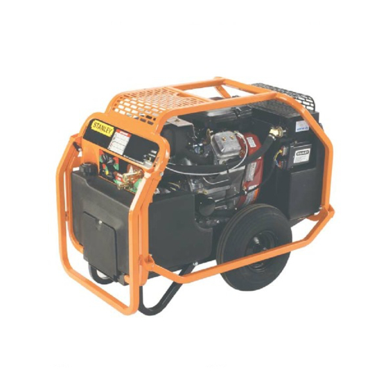
- Page 1 GT18B01 HYDRAULIC POWER UNIT WARNING AFETY PERATION AND AINTENANCE SERVICE MANUAL Stanley Hydraulic Tools 3810 SE Naef Road Milwaukie OR 97267-5698 503-659-5660 Copyright © 2004, The Stanley Works FAX 503-652-1780 OPS/MAINT USA www.stanley-hydraulic-tools.com 65466 9/2004 Ver 1...
-
Page 3: Table Of Contents
REPAIRS AND / OR SERVICE TO THIS TOOL MUST ONLY BE DONE BY AN AUTHORIZED AND CERTIFIED DEALER. For the nearest authorized and certifi ed dealer, call Stanley Hydraulic Tools at the number listed on the back of this manual and ask for a Customer Service Representative. - Page 4 Hereby certify that the construction plant or equipment specified hereunder: 1. Manufacturer: Stanley Hydraulic Tools, 3810 Naef Road, Milwaukie, Oregon USA 2. Representative in the Union: Stanley Svenska AB, Box 9054, 400 92 Göteborg, SWEDEN 3. Category: Hydraulic Power Unit 4.
-
Page 5: Safety Symbols
SAFETY SYMBOLS Safety symbols and signal words, as shown below, are used to emphasize all operator, maintenance and repair actions which, if not strictly followed, could result in a life-threatening situation, bodily injury or damage to equip- ment. This is the safety alert symbol. It is used to alert you to potential personal injury hazards. -
Page 6: Safety Precautions
In addition to this manual, read and understand safety and operating instructions in the Engine Operation Manual furnished with the power unit. The GT18B01 Hydraulic Power Unit will provide safe and dependable service if oper- ated in accordance with the instructions given in this manual. Read and understand this manual and any stickers and tags attached to the Power Unit. -
Page 7: Tool Stickers & Tags
TOOL STICKERS & TAGS 62302 Power Unit Dash Decal 62300 Single Circuit 28322 65458 CE Decal Sound Power Decal DANGER CHOKE PULL TO START PUSH TO RUN 62302 AUTO IDLE AUTO IDLE 62300... -
Page 8: Hydraulic Hose Requirements
HOSE SAFETY TAGS To help ensure your safety, the following DANGER tags are attached to all hose purchased from Stanley Hydrau- lic Tools. DO NOT REMOVE THESE TAGS. -
Page 9: Htma Requirements
HTMA REQUIREMENTS TOOL CATEGORY HYDRAULIC SYSTEM REQUIREMENTS TYPE I TYPEII TYPEIII TYPE RR FLOW RATE 4-6 gpm 7-9 gpm 11-13 gpm 9-10.5 gpm (15-23 lpm) (26-34 lpm) (42-49 lpm) (34-40 lpm) TOOL OPERATING PRESSURE 2000 psi 2000 psi 2000 psi 2000 psi (at the power supply outlet) (138 bar) -
Page 10: Operation
fi ttings. Follow These fl uids are recommended by Stanley. Other fl uids the instructions furnished with the selected thread sealant. that meet or exceed the specifi cations of these fl uids may... - Page 11 OPERATION DO NOT OVERTIGHTEN THE FITTINGS. CONTROL PANEL 5. BATTERY The supplied 12 Volt DC battery is a non-spillable, mainte- RETURN PRESSURE nance-free battery and is fully charged. H.T.M.A. 1/2 INCH FE- Make sure the battery cables are tight and charging circuit MALE QUICK DISCON- functions are operating properly.
-
Page 12: Controls
OPERATION At times it may be neccessary to reset the controller. This could happen if a fault occurs in the controller. For ex- CONTROLS ample, excessive engine speed. If a fault does occur the power unit will return to an idle and the operator will have This unit is equipped with an advanced proportional engine no control of the unit. -
Page 13: Cold Weather Startup
OPERATION COLD WEATHER STARTUP 1. Use the procedures described under "STARTUP" and then follow the procedure below. 2. Hydraulic fl uids are thicker in cold weather. Therefore, it is recommended that the engine be run at low idle long enough to bring the fl uid temperature up to a minimum of 50°F/10°C. -
Page 14: Routine Maintenance
ROUTINE MAINTENANCE ENGINE MAINTENANCE STORAGE Follow the maintenance schedule and general maintenance • Clean the unit thoroughly before storage. Do not use instructions in the engine maintenance and operation water pressure. manual furnished with the power unit. • Always store the unit in a clean and dry facility. HYDRAULIC SYSTEM MAINTENANCE •... -
Page 15: Programmable Controller
Stanley controller. Stanley Hydraulic Tools The Stanley controller is capable of identifying certain fault recommends that an authorized and certifi ed conditions and alerting the user to them. A fl ashing LED dealer perform calibration of this unit. - Page 16 CODE FAULT SHUTDOWN CORRECTIVE ACTION APECS unit not calibrated Have engine serviced by an Authorized Stanley Dealer. Engine speed excessive Have engine serviced by an Authorized Stanley Dealer. Engine speed unusually low Have engine serviced by an Authorized Stanley Dealer.
-
Page 17: Testing & Troubleshooting
1. Set the fl ow selector switch to the OFF (center) position. 2. Set the throttle control switch to AUTO-OFF position. 3. Connect the Stanley Circuit Tester across two hose ends (where the tool would normally be connected). 4. Fully open the tester restrictor valve (counterclockwise). -
Page 18: Troubleshooting
TROUBLESHOOTING PROBLEM CAUSE REMEDY Engine will not start. Flow selector switch not in the Make sure the fl ow selector switch is in OFF position. the OFF position when starting. Battery not connected. Attach battery cables, check wires. Weak battery. Test battery, charge or replace. -
Page 19: Specifications
SPECIFICATIONS Engine: ................................18 hp Briggs Capacity ..................One 5 gpm/19 lpm Circuit or One 8 gpm/30 lpm Circuit Length: ................................36 in. / 91.4 cm Width: ................................23 in: / 58.4 cm Height: ................................29.5 in. / 74.9cm Weight (Wet): Single Circuit Briggs ......................330 lbs / 149.6 kg Fuel Tank Capacity: ............................ -
Page 20: Service
SERVICE 3. Disconnect the wiring harness plugs from the pressure GENERAL switch (26, fi g. 2) and from the directional valve (27, fi g. 2). Service instructions in this section are limited to parts and 4. While holding the manifold assembly in one hand, re- components other than the engine and hydraulic pump. - Page 21 SERVICE 2. Disconnect the wiring harness (See Figure 4, Wiring Remove the retaining ring and washer (48, 49, fi g. 1) and Diagrams for the correct connections). remove the wheel. The engine and hydraulic tank can now be removed from the side of the unit. 3.Follow steps 1 through 4 under "Manifold Assembly Re- moval".
- Page 22 SERVICE Assemble the bushing and blower hub with the bolts IMPORTANT inserted (but not tightened) through the drilled holes in the blower hub and into the tapped holes in the bushing. Never change any wiring connections. If With the key in the shaft, slide assembly into position wires are not connected correctly, compo- on the shaft and tighten the setscrew over the key (if nenets could be damaged.
- Page 23 SERVICE HYDRAULIC TANK, COOLER & FILTER HYDRAULIC PUMP, COUPLING AND PUMP ASSEMBLY (see fi gure 1, 2 & 3) MOUNT (see fi gure 1) 1. First remove the hydraulic fl uid from the tank by either 1. Drain the hydraulic tank. pumping it out with a portable drill pump or draining it into a container.
-
Page 24: Figure 1. Briggs Engine Assembly
FIGURE 1. BRIGGS ENGINE ASSEMBLY... -
Page 25: Figure 1. Briggs Engine Parts List
FIGURE 1. BRIGGS ENGINE PARTS LIST ITEM DESCRIPTION ITEM DESCRIPTION 65467 Engine Controller 36150 Muffl er 40433 Hex Flange Bolt 5/16-18 x 1/2 65456 Spark Arrester 58897 Frame Base Weldment 36151 Heat Shield 58918 Wheel & Tire 36152 Screw, Hex Washer 58917 Axle 59007... -
Page 26: Figure 2. Frame Parts
FIGURE 2. FRAME PARTS ITEM DESCRIPTION ITEM DESCRIPTION 370502 Capscrew, 5/16 in. -18 UNC Cap (Included with Item 27) 03906 Nylock Nut, 5/16 in. -18 UNC 60958 Coil 62270 Handle, Rear Lift 28322 CE Decal 58857 Coupler, Male 3/8 in., -8 SAE 65458 Sound Power Decal 58856... -
Page 27: Figure 3. Hoses, Fittings & Clamps
FIGURE 3. HOSES, FITTINGS & CLAMPS ITEM DESCRIPTION 59130 Manifold Assy, Single Circuit 59104 Hose Barb, 3/4 in. Hose x 3/4 in. Pipe 62199 Hose Clamp Elbow, 45° Straight Thread 350000 02773 Adapter 58569 Elbow, 90° 58943 Hose Connector, Straight Thread 350104 40364 Elbow, 45°... -
Page 28: Figure 4B. Main Power Unit Wiring Harness
FIGURE 4B. MAIN POWER UNIT WIRING HARNESS HARNESS PART NUMBER 65147 THROTTLE CONTROL SWITCH (NOTE: PLUG BEHIND SWITCH WITH BLUE & YELLOW WIRES GOES TO SWITCH ON TOP) FLOW CONTROL SWITCH HOUR METER DIRECTIONAL VALVE START SWITCH BLACK MANIFOLD ASSY PRESSURE SWITCH TO STARTER SOLENOID PLUG TOP RESSURE SWITCH... -
Page 29: Warranty
SEALS & DIAPHRAGMS: Seals and diaphragms installed in new tools are warranted to be free of defects in material and/or workmanship for a period of 6 months after the date of fi rst usage, or for a period of 2 years from the shipping date from Stanley, whichever period expires fi rst. - Page 30 Stanley Hydraulic Tools 3810 SE Naef Road Milwaukie OR 97267-5698 503-659-5660 FAX 503-652-1780 www.stanley-hydraulic-tools.com...
Need help?
Do you have a question about the GT18B01 and is the answer not in the manual?
Questions and answers