Table of Contents
Advertisement
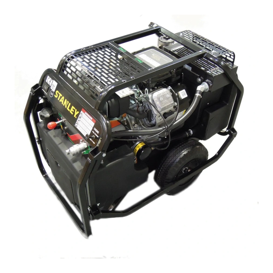
Infrastructure
GT & HP Power Unit Technical Bulletin
12/2019 Ver. 1
What has changed?
For all non-diesel models of GT and HP Power Units, a shipping cap will be installed over the breather valve of the hydraulic oil tank.
This shipping cap and attached warning tag must be removed before using the power unit. Failure to remove this cap may cause catastrophic power unit
damage.
Why has the change taken place?
During shipping, it is possible for hydraulic oil to escape the hydraulic oil reservoir through the breather valve. In order to eliminate hydraulic oil spillage,
STANLEY will install a cap over the breather valve before the power unit is shipped.
How to Remove the Shipping Cap
1.
Unpack the power unit.
2.
Locate the shipping cap installed over the breather valve.
Note: The shipping cap will be connected to a large information tag.
Plug and Tag Installed
3.
Grasp the base of the cap, pull it off of the breather valve and discard it.
Note: If your power unit breather valve does not have a cap installed, you may use the power unit normally.
Pump damage can occur if action is not taken! Remove the attached
shipping cap and tag before using this power unit. Failure to remove the
shipping cap could cause catastrophic damage.
Plug and Tag Removed
Advertisement
Table of Contents

Related Manuals for Stanley HP8


Summary of Contents for Stanley HP8
- Page 1 During shipping, it is possible for hydraulic oil to escape the hydraulic oil reservoir through the breather valve. In order to eliminate hydraulic oil spillage, STANLEY will install a cap over the breather valve before the power unit is shipped.
- Page 3 HYDRAULIC POWER UNIT (HP8BA, HP8BD, HP8BM) USER MANUAL Safety, Operation and Maintenance © 2014 STANLEY Black & Decker, Inc. New Britain, CT 06053 U.S.A. 81116 1/2022 Ver. 7 Model HP8 Only...
- Page 4 Disposizioni speciali: Misurazioni Representative in the Union: Patrick Vervier, Stanley Dubuis 17-19, rue Jules Berthonneau-BP 3406 41034 Blois Cedex, France. Vertreter in der Union/Représentant dans l’union/Representante en la Union/Rappresentante presso l’Unione Done at/Ort/Fait à/Dado en/Fatto a Stanley Hydraulic Tools, Milwaukie, Oregon USA...
-
Page 5: Table Of Contents
REPAIRS AND / OR SERVICE TO THIS TOOL MUST ONLY BE DONE BY AN AUTHORIZED AND CERTIFIED DEALER. For the nearest certified dealer, call STANLEY Infrastructure at (503) 659-5660 and ask for a Customer Service Representative. 4 ► HP8 User Manual... -
Page 6: Safety Symbols
Always observe safety symbols. They are included for your safety and for the protection of the tool. LOCAL SAFETY REGULATIONS Enter any local safety regulations here. Keep these instructions in an area accessible to the operator and maintenance personnel. HP8 User Manual ◄ 5... -
Page 7: Safety Precautions
HP8 power unit. • Keep clear of hot engine exhaust. The HP8 will provide safe and dependable service if operated in accordance with the instructions given in • Do not add fuel to the power unit while it is running this manual. -
Page 8: Tool Stickers & Tags
HP8BA Only 73306 66653 Guaranteed Sound Lift Point Decal Power Level Decal HP8BA HP8BA Only HP8BM 88423 Address Decal HP8BA Only 24053 High Temperature Warning Sticker HP8BM 74759 Power Unit Dash Decal 76760 Single Circuit Decal HP8 User Manual ◄ 7... -
Page 9: Hose Types
This hose is not certifi ed non-conductive and must never be used near electrical conductors. HOSE SAFETY TAGS To help ensure your safety, the following DANGER tags are attached to all hose purchased from STANLEY. DO NOT REMOVE THESE TAGS. -
Page 10: Hose Recommendations
HOSE RECOMMENDATIONS HP8 User Manual ◄ 9... -
Page 11: Htma / Ehtma Requirements
2000 psi 2000 psi (At the power supply outlet) (172 bar) (138 bar) (138 bar) (138 bar) (138 bar) Note: These are general hydraulic system requirements. See tool specifi cation page for tool specifi c requirements. 10 ► HP8 User Manual... -
Page 12: Operation
PREPARATION FOR USE quick disconnect fittings (NPT). H.T.M.A. approved quick disconnect couplings are installed Do not operate HP8 until you have completed the following to hydraulic hoses so that the direction of oil flow is always steps: from the male to the female coupling. Additional fittings, such as reducers or adapter fittings, are not required. - Page 13 STARTUP SHUTDOWN 1. Toggle the flow switch to the “FLOW OFF” position. Note: HP8 will not start unless the Flow Switch is in the 1. Toggle the flow switch to the “FLOW OFF” position. "FLOW OFF" position. 2. Allow the engine to idle at the 5 GPM/20 LPM flow 2.
-
Page 14: Maintenance & Testing
Follow the maintenance instructions provided in the engine “Operating & Maintenance Instructions” manual. GENERAL HYDRAULIC SYSTEM MAINTENANCE Tests should be performed periodically to ensure HP8 is operating at maximum efficiency. STANLEY Circuit Tester • Check hydraulic fluid level daily and fill, if needed. -
Page 15: Troubleshooting
Visually check the suction hose for a kink. The hose should have a smooth curve. The solenoid is not working. Check electrical connections to the solenoid. Replace if necessary. The attached tool is defective. Refer to the tool manual. 14 ► HP8 User Manual... -
Page 16: Hp8Bm Maas Support Tool Package
POWER UNITS,TRACHORSE & GAS/FUEL DRIVEN EQUIPMENT: A1. Federal Emission Component Compliance 40CFR part 1060.120 STANLEY warrants all fuel system emission components for 2 years from the date of original purchase provided there has been no abuse, neglect, modifications or improper maintenance. -
Page 17: Hp8 Frame Parts Illustration
Lift Handle (HP8BM) unit or hydraulic oil tank 58976 Flange Bolt AFTER manufactured 1/1/2021 62267 Rear Lift Handle 59095 Flange Nut 66063 Rear Lift Handle (HP8BM) 08080 Handle Grip (HP8BM) 58916 Handle Lock 66707 Carry Handle (HP8BM) 16 ► HP8 User Manual... -
Page 18: Hp8 Control Panel Parts Illustration
HP8 CONTROL PANEL PARTS ILLUSTRATION ITEM # PART # DESCRIPTION ITEM # PART # DESCRIPTION 74759 Dash Decal 60958 Solenoid Coil 62298 Choke Cable 76760 Single Circuit Decal 204332 Throttle Knob 60962 Capscrew 17134 58631 Swivel (HP8BM) 76758 Throttle Rod... -
Page 19: Hp8 Engine Parts Illustration - Front
HP8 ENGINE PARTS ILLUSTRATION - FRONT ITEM # PART # DESCRIPTION ITEM # PART # DESCRIPTION 62303 Blower Wheel 43687 Capscrew 80984 Lock Washer 40080 Filter Assembly 80986 Hex Head Capscrew 51292 Standard Thread Union 59077 Hydraulic Oil Tank 59091... -
Page 20: Hp8 Engine Parts Illustration - Back
HP8 ENGINE PARTS ILLUSTRATION - BACK ITEM # PART # DESCRIPTION ITEM # PART # DESCRIPTION 72317 Hose Clamp 72571 Fuel Vapor Hose 72451 Hose Clamp 73050 Fuel Tank 62324 Heat Shield 04303 Battery 65456 Spark Arrester 60921 Battery Cover... -
Page 21: Hp8 Engine Parts Illustration - Base
HP8 ENGINE PARTS ILLUSTRATION - BASE 10 11 12 ITEM # PART # DESCRIPTION 76754 Engine 64991 Hex Head Capscrew 56709 Cable Clamp 01212 Pipe Plug 12787 Flange Nut 24287 Hose Clamp 58897 Frame Base Weldment 58917 Axle 56633 Wheel and Tire... -
Page 22: Hoses, Fittings And Clamps
HOSES, FITTINGS AND CLAMPS ITEM # PART # DESCRIPTION 58943 Hose 62199 Hose Clamp 40364 45° Elbow Fitting 59105 Hose Barb 59089 Hose 59088 Hose 58569 90° Elbow Fitting 350000 45° Fitting 02773 Adapter 350104 Connector HP8 User Manual ◄ 21... -
Page 23: Main Wiring Harness
PART NUMBER 76710 Start Switch Hour Meter Positive battery cable to starter Solenoid Coil Black solenoid (Red) Engine Kill (Black) Flow Switch Starter Relay Black Fuel Shutoff Starter Solenoid (Red) (Green) Battery Oil Pressure Switch 22 ► HP8 User Manual... -
Page 24: Electrical Schematic
ELECTRICAL SCHEMATIC HP8 User Manual ◄ 23... -
Page 25: Hold Down Kit & Installation
Backup Bar 66756 Foot Hold Down Weldment 66933 Carriage Bolt 66934 Lanyard 66935 Quick Release Pin, 3/8 x 1 66936 Quick Release Pin 66937 Yoke 66939 Yoke, Male 370254 Capscrew, 1/2-13 x 3 371500 Locknut, 1/2-13 24 ► HP8 User Manual... - Page 26 Foot hold down weldment bolted through grating with backup bar under grating. To install the power unit facing the opposite direction, rotate the grating on the MAAS Trailer 180°. HP8 User Manual ◄ 25...
- Page 28 STANLEY Infrastructure 6430 SE Lake Road Portland, Oregon 97222 USA (503) 659-5660 / Fax (503) 652-1780 www.stanleyinfrastructure.com...
Need help?
Do you have a question about the HP8 and is the answer not in the manual?
Questions and answers