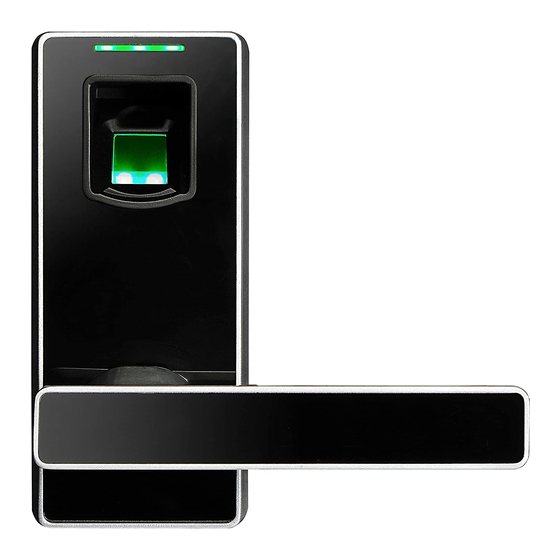
ZKTeco PL10 Installation Instruction
Hide thumbs
Also See for PL10:
- User manual (16 pages) ,
- Installation manual (10 pages) ,
- User manual (19 pages)
Table of Contents
Advertisement
Quick Links
Advertisement
Table of Contents

Summary of Contents for ZKTeco PL10
- Page 1 Installation Instruction PL10/ML10 Version: 2.0...
-
Page 2: Before Installation
Before Installation Diagram... -
Page 3: Packing List
Packing List Mounting Hardware Package Mounting Hardware Package for door thickness of 39-46mm for door thickness of 47-54mm 64mm 7 2mm 35mm 40mm 30mm 35mm... -
Page 4: Door Preparation
Door Preparation 1. Check the door thickness and prepare the corresponding mounting hardware package. Door Thickness H Spindle Length J Screw Length M Screw Length L Screw Length (mm) (mm) (mm) (mm) (mm) 30~38 39~46 47~54 55~60 Note: The standard lock includes 2 mounting hardware packages only, which are used for the door thickness of 39-46mm and 47-54 mm separately. - Page 5 3. Check the required backset (60mm or 70mm). 70mm 60mm Note2: The latch has two backset options: 60mm and Note1: Installation template has the backset options of both 60mm and 70mm. 70mm, please choose either one as required.
- Page 6 Remarks 1. New lock is configured to grant any fingerprint access. 2. The lock is equipped with mechanical keys for manual unlocking. Remove mechanical keys from the package and keep them in a safe place. 3. To power up the lock, four alkaline AA batteries (not included) are required. Non-alkaline and rechargeable batteries are NOT recommended.
-
Page 7: Installation
Installation 1. Drill holes on the door. 2. Install the latch (D). center line of the handle desired handle height Note1: Align the template along the vertical center line of the latch(D) at the desired handle height, and tape it to the door. Note2: Mark the holes first, and then start drilling. - Page 8 3. Install outdoor unit (B) with gasket (C) and spindle(H) on the door. Correct Position: T he small triangle must be vertically upward. This position is wrong .
- Page 9 4. Install mounting plate (I) with gasket (C) on the door. 5. Install indoor unit (K). Note : Push cable into the hole first.
-
Page 10: Insert Batteries
6. Insert batteries. 7. Mark and drill holes for the strike. (5/64") 12mm (15/32") 21mm (53/64") 35mm (35/64") (1-3/8") 8. Test the lock by rotating the back handle and using the mechanical key (A). Note : When the door is l ocked and the clutch is idle, the front handle can be turned, but the door will remain locked.


Need help?
Do you have a question about the PL10 and is the answer not in the manual?
Questions and answers