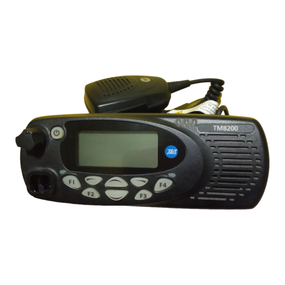
Tait TM8200 User Manual
Hide thumbs
Also See for TM8200:
- Accessories manual (140 pages) ,
- Operator's manual (84 pages) ,
- Installation and operation manual (41 pages)
Table of Contents
Advertisement
Directive 1999/5/EC Declaration of Conformity
da
Dansk
Undertegnede Tait Electronics Ltd erklærer
herved, at følgende udstyr TMAB1C,
TMAD1C & TMAH5C overholder de
væsentlige krav og øvrige relevante krav i
direktiv 1999/5/EF.
Se endvidere: http://eudocs.taitworld.com/
de
Deutsch
Hiermit erklärt Tait Electronics Ltd die Übere-
instimmung des Gerätes TMAB1C, TMAD1C
& TMAH5C mit den grundlegenden
Anforderungen und den anderen relevanten
Festlegungen der Richtlinie 1999/5/EG.
Siehe auch: http://eudocs.taitworld.com/
el
Ελληνικός
Με την παρουσα Tait Electronics Ltd
δηλωνει οτι TMAB1C, TMAD1C &
TMAH5C συµµορφωνεται προσ τισ
ουσιωδεισ απαιτησεισ και τισ λοιπεσ
σχετικεσ διαταξεισ τησ οδηγιασ 1999/5/ΕΚ.
βλέπε και: http://eudocs.taitworld.com/
en
English
Tait Electronics Ltd declares that this
TMAB1C, TMAD1C & TMAH5C complies
with the essential requirements and other
relevant provisions of Directive 1999/5/EC.
See also: http://eudocs.taitworld.com/
es
Español
Por medio de la presente Tait Electronics Ltd
declara que el TMAB1C, TMAD1C &
TMAH5C cumple con los requisitos esen-
ciales y cualesquiera otras disposiciones apli-
cables o exigibles de la Directiva 1999/5/CE.
Vea también: http://eudocs.taitworld.com/
fi
Suomi
Tait Electronics Ltd vakuuttaa täten että
TMAB1C, TMAD1C & TMAH5C tyyppinen
laite on direktiivin 1999/5/EY oleellisten
vaatimusten ja sitä koskevien direktiivin
MMA-00003-02 Issue 2
© Tait Electronics Ltd September 2004. All rights reserved. Directive 1999/5/EC Declaration
muiden ehtojen mukainen.
Katso: http://eudocs.taitworld.com/
fr
Français
Par la présente, Tait Electronics Ltd déclare
que l'appareil TMAB1C, TMAD1C &
TMAH5C est conforme aux exigences
essentielles et aux autres dispositions perti-
nentes de la directive 1999/5/CE.
Voir aussi: http://eudocs.taitworld.com/
it
Italiano
Con la presente Tait Electronics Ltd dichiara
che questo TMAB1C, TMAD1C & TMAH5C
è conforme ai requisiti essenziali ed alle
altre disposizioni pertinenti stabilite dalla
direttiva 1999/5/CE.
Vedi anche: http://eudocs.taitworld.com/
nl
Nederlands
Hierbij verklaart Tait Electronics Ltd dat het
toestel TMAB1C, TMAD1C & TMAH5C in
overeenstemming is met de essentiële
eisen en de andere relevante bepalingen
van richtlijn 1999/5/ EG.
Zie ook: http://eudocs.taitworld.com/
pt
Português
Tait Electronics Ltd declara que este
TMAB1C, TMAD1C & TMAH5C está
conforme com os requisitos essenciais e
outras provisões da Directiva 1999/5/CE.
Veja também: http://eudocs.taitworld.com/
sv
Svensk
Härmed intygar Tait Electronics Ltd att
denna TMAB1C, TMAD1C & TMAH5C står
I överensstämmelse med de väsentliga
egenskapskrav och övriga relevanta
bestämmelser som framgår av direktiv
1999/5/EG.
Se även: http://eudocs.taitworld.com/
Advertisement
Chapters
Table of Contents

Related Manuals for Tait TM8200


Summary of Contents for Tait TM8200
- Page 1 Tait Electronics Ltd vakuuttaa täten että 1999/5/EG. TMAB1C, TMAD1C & TMAH5C tyyppinen Se även: http://eudocs.taitworld.com/ laite on direktiivin 1999/5/EY oleellisten vaatimusten ja sitä koskevien direktiivin MMA-00003-02 Issue 2 © Tait Electronics Ltd September 2004. All rights reserved. Directive 1999/5/EC Declaration...
-
Page 3: About This Guide
About this guide This user’s guide provides information about TM8200 radios and is divided into two parts. Part 1 explains how the TM8250 radio with the graphical display operates. Part 2 outlines the installation procedure for all TM8200 radios. If you need further assistance or your radio does not operate as you expect, contact your radio provider. -
Page 4: Changes To This Guide
Copyright information All information contained in this guide is the property of Tait Electronics Ltd. All rights are reserved. These guides may not, in whole or in part, be copied, photocopied, reproduced, translated, stored, or reduced to any electronic medium or machine-readable form, without prior written permission from Tait Electronics Ltd. - Page 5 Your radio’s settings Use the following table to list your radio’s programmed settings. Function key settings quick access menus: Frequently used channels and groups Description Description...
-
Page 9: Table Of Contents
Part 1: Radio operation About this guide ................3 Important safety information ............... 3 Safety warnings used in this guide .............. 3 Feedback about this guide ................3 Changes to this guide ................. 4 Copyright information ................. 4 Disclaimer ....................4 Safety and compliance warnings .......... - Page 10 Making a call using your address book ............32 Making an emergency call ................ 34 Receiving a call ..................34 Hearing faint and noisy signals ..............34 Troubleshooting .................37 When your radio won’t turn on ..............37 Removing the microphone ................ 37 Removing the radio from the vehicle ............
-
Page 11: Safety And Compliance Warnings
Safety and compliance warnings Radio frequency exposure information For your own safety and to ensure you comply with the Federal Communication Commission’s (FCC) radio frequency (RF) exposure guidelines, please read the following information before using this radio. Using this radio You should use this radio only for work-related purposes (it is not authorized for any other use) and if you are fully aware of, and can exercise control over, your exposure to RF energy. -
Page 12: Radio Frequency Emissions Limits In The Usa
0.9m (35 inches) between people and the antenna. This is the minimum safe distance. Use the radio only with Tait-approved antennas and attachments, and make only authorized modifications to the antenna otherwise you could damage the radio and violate FCC regulations. -
Page 13: Health, Safety And Electromagnetic Compatibility In Europe
Note: Changes or modifications to this device that are not expressly approved by Tait Electronics Ltd may make its use illegal. Health, safety and electromagnetic compatibility in Europe In the European Community, radio and telecommunications equipment is regulated by Directive 1999/5/EC, also known as the Radio and Telecommunications Terminal Equipment (R&TTE) directive. -
Page 14: En 60950 Requirements (25 Watt Radios)
cover the electromagnetic compatibility of electrical or elec- tronic equipment fitted to automotive vehicles. Note: To meet the requirements of Directive 72/245/EEC (as amended by 95/54/EC) installation of this product in a vehicle must be performed according to the instructions provided, and any guidelines of the vehicle manufacturer. -
Page 15: Getting Started
Getting started This section provides a brief description of your radio’s controls and indicators and explains how to use the radio’s menus. The following topics are covered in this section: radio controls radio indicators navigating your radio’s menus viewing your radio’s function key settings. - Page 16 press-to-talk (PTT) key radio status LEDs green microphone amber speaker display on/off key volume control microphone socket function keys Main menu scroll keys 1 to 4 left selection key right selection key Symbol Name Function PTT key press and hold to transmit and release to listen volume control rotate to change the speaker volume...
-
Page 17: Radio Indicators
Radio indicators The radio display, LED indicators and the radio’s audible tones all combine to give you information about the state of your radio. The most common operation of the radio display and indica- tors is described in the following sections. Note: The way these indicators behave may be affected by the way your radio is programmed. - Page 18 Radio display icons Icon Meaning received signal strength indicator (RSSI) (green LED glowing): the more bars on this indicator, the stronger the signal being received by your radio. transmit power level (red LED glowing): the more bars on the indicator, the higher the power level of your transmission MPT network: your radio has access to an MPT network...
-
Page 19: Led Indicators
LED indicators Meaning glowing: your radio is transmitting (transmit) flashing: your transmit timer is about to expire, or your radio is stunned, or your call time is about to expire (MPT trunked mode) green glowing: you are receiving (receive) flashing: you have received a call amber glowing: your radio is scanning a group of (scanning or... -
Page 20: Navigating Your Radio's Menus
Navigating your radio’s menus Your radio has a number of menus available, each containing lists or submenus. The menus available will depend on the way your radio is programmed. Using the Main menu Whenever Menu appears above the right selection key , you are able to open the Main menu by pressing... -
Page 21: Viewing Your Radio's Function Key Settings
Using the left selection key Quick Access menu Your radio may be programmed so that your left selection key acts as a shortcut to another frequently used menu. If this menu has been programmed, the text for left selec- tion key corresponds to the menu. To use this Quick Access menu, press your left selection key , and the associated menu appears. -
Page 22: Basic Operation
Basic operation This section describes the basic operations of your radio. The following topics are covered in this section: turning the radio on and off entering your personal identification number adjusting the speaker volume turning on control-head backlighting. Turning the radio on and off Give a long press of the on/off key to turn the radio either on or off. -
Page 23: Adjusting The Speaker Volume
Adjusting the speaker volume Rotate the volume control clockwise to increase the speaker volume and counterclockwise to decrease the volume. The volume control also changes the volume level of the radio’s audible indicators. Note: Your radio may be programmed with a minimum volume level. - Page 24 Toggling backlighting on and off by using the Main menu When backlighting is turned on using the menu, it remains on until the setting is changed to off, regardless of radio activity. Select Menu>Radio Settings> Display Settings>Backlighting. In the Backlighting menu, chose either On or Off.
-
Page 25: Operating In Conventional Mode
Operating in conventional mode The following topics are covered in this section: selecting a channel or scanning group selecting a zone checking that a channel is clear making a call making a local call making a call using your address book making an emergency call receiving a call hearing faint and noisy... -
Page 26: The Main Menu
Selecting a channel or scan group by using the Main menu Select Menu>Channels. In the Channels menu, scroll through the list of channels and scan groups until the channel or scan group you want appears. Press Done. If you have selected a scan group, the amber LED glows and the scanning icon appears in... -
Page 27: Selecting A Zone
Selecting a zone A zone is a collection of channels. To select a zone you may be able to either: use the Main menu, or use your Quick Access menu. Selecting a zone by using the Main menu Select Menu>Zones. In the Zones menu, scroll through the list of zones until the one you want appears. -
Page 28: Checking That A Channel Is Clear
Selecting a zone by using your Quick Access menu Press one of the scroll keys to open the Zones menu. Alternatively, the left selection key may be programmed as your Quick Access menu. In this case, press the left selection key to access the Zones menu. - Page 29 Note: Your radio may be programmed to activate monitor whenever the microphone is off the microphone clip. To activate monitor, you may be able to either: remove the microphone from the microphone clip, use a programmed function key, or use the Main menu. Activating monitor by using a function key Press the monitor function key to activate monitor and hear any traffic on the channel.
-
Page 30: Making A Call
Press Select. While monitor is on, the green LED flashes continually and the monitor icon appears in the icon bar. Making a call Select the required channel or scan group. Check that the channel is clear. If the green LED is glowing, the channel is busy and you may not be able to transmit. -
Page 31: Making A Local Call
Making a local call Each channel on your radio may have one or more local calls programmed. To make a local call you may be able to either: use a programmed function key, use the Main menu, or use your Quick Access menu. Making a local call by using a function key Select the required channel. -
Page 32: Making A Call Using Your Address Book
Making a local call by using your Quick Access menu Select the required channel. Press one of the scroll keys to open the Local Calls menu. Scroll through the list of local calls until the call you want appears. Press Send. The call details appear in the display, the red LED glows and the transmit icon... - Page 33 The call details appear in the display, the red LED glows and the transmit icon appears in the icon bar. Making an address-book call by using the Main menu Select Menu>Address Book. In the Address Book menu, scroll through the list of calls until the call you want appears.
-
Page 34: Making An Emergency Call
Press Send. The call details appear in the display, the red LED glows and the transmit icon appears in the icon bar. Making an emergency call You may be able to activate emergency mode by using a programmed function key. Press the function key programmed for emergency mode and an emergency call is sent to your dispatcher, or some other predetermined location. -
Page 35: Function Key
To activate squelch override, you may be able to either: use a programmed function key, or use the Main menu. Turning squelch override on and off by using a function key Press the function key programmed for squelch override to unmute the radio. The message Squelch override activated appears on the display. - Page 36 While squelch override is on, the green LED flashes continu- ally and the squelch override icon appears in the icon bar. Squelch override remains on until there is a further long key press. Activating squelch override by using the Main menu Select Menu>Radio Settings>...
-
Page 37: Troubleshooting
Troubleshooting The following topics are covered in this section: when your radio won’t turn on removing the microphone removing the radio from the vehicle describing the radio’s audible tones. When your radio won’t turn on If the red, green and amber LEDs on the control head do not light up when the radio is turned on, it is likely that no power is reaching the radio. -
Page 38: Removing The Radio From The Vehicle
Removing the radio from the vehicle Switch off the radio. Unscrew the four thumb screws that secure the radio to the U-bracket Carefully lift the radio clear of the U-bracket. Disconnect the antenna and power cable from the rear of the radio. Describing the radio’s audible tones The following table summarizes the radio’s audible tones. - Page 39 Action and tone Meaning one short, low- function deactivated: a function key has pitched beep been pressed and the corresponding function has been turned off one long, low- invalid key press: the action you have pitched beep attempted is not permitted, or transmission inhibited: you have attempted to transmit but for some reason transmission is not permitted at this time...
-
Page 40: Notes
Notes 40 Notes... - Page 41 Installing the power cable ................. 51 Mounting the U-bracket ................53 Installing the radio in the U-bracket ............54 Checking the installation ................54 Other installation options ................. 55 Tait general software licence agreement ......... 56 Radio installation procedures 41...
-
Page 42: Installation Warnings
Installation warnings The following topics are covered in this section: safe radio mounting interference with the vehicle’s electronic systems preparation when drilling holes vehicles powered by liquefied petroleum gas (LPG) radio installation in gas or fuel tankers non-standard radio installations negative ground supply. -
Page 43: Preparation When Drilling Holes
The LPG container space shall be vented to the outside of the vehicle. Radio installation in gas or fuel tankers Special conditions must be observed when installing a radio in gas and fuel tankers. Consult your radio provider or Tait-accredited service centre for more details. Installation warnings 43... -
Page 44: Non-Standard Radio Installations
10mm (3/8 inch) between the bottom surface of the radio chassis and the mounting surface. This is illustrated in the following diagram. 10mm (3/8 inch) mounting surface Negative ground supply TM8200 radios are designed to operate only in a negative ground system. 44 Installation warnings... -
Page 45: Installation Planning
Installation planning The procedures outlined in this and the following sections are for installing a TM8200 radio in a vehicle, using a standard U-bracket. The following topics are covered in this section: MPT 1362 code of practice checking equipment installation tools selecting the mounting position. -
Page 46: Installation Tools
— fuse holders — receptacles for a remote speaker (speaker not included) — BNC or mini-UHF antenna plug. Installation tools The following installation tools may be required: portable drill and drill bit Pozidriv screwdriver 8mm (5/16 inch) socket (or Pozidriv screwdriver) BNC or mini-UHF crimp tool fuse crimp tool in-line RF power meter capable of measuring forward and... -
Page 47: Radio Installation
Radio Installation The following topics are covered in this section: installing and removing the control head installing the microphone installing the antenna installing the power cable mounting the U-bracket installing the radio in the U-bracket checking the installation other installation options. - Page 48 Removing the control head Caution: During this procedure, take care that the control- head seal is not damaged. Damage to this seal reduces environmental protection. On the underside of the radio, insert a 5mm (3/16 inch) flat-bladed screwdriver between the control head and the control-head seal, in either position Insertion points are lever points and are indi-...
-
Page 49: Installing The Microphone
Installing the microphone A microphone and microphone clip are only used for radios with a user interface. Caution: The microphone grommet must be installed when- ever the microphone is plugged into the micro- phone socket. When installed, the grommet has two functions: to prevent damage to the microphone socket when there is movement of the microphone cord, and... -
Page 50: Installing The Antenna
Installing the antenna Install the external antenna according to the supplier’s instructions. Good quality 50 ohm coaxial cable must be used, such as RG58 or UR76. Caution: The cable should be routed in a manner that mini- mizes coupling into the electronic control systems of the vehicle. -
Page 51: Installing The Power Cable
Installing the power cable One end of the power cable is connected to the vehicle battery and the other end plugs into the radio’s power connector. Power connector The following table explains the pin allocations for the power connectors on both 25W and 40W/50W radios. Signal name Description AGND earth return for radio body... - Page 52 vehicle owner has the necessary information to make all electronic equipment function correctly after battery reconnection. Caution: If the battery is not disconnected, exercise extreme caution throughout the installation and install the fuses only when the installation is ready to be checked (see “Checking the installation”...
-
Page 53: Mounting The U-Bracket
Mounting the U-bracket The U-bracket can be used to install the radio on the dash- board or on any sufficiently flat surface, using the self-drilling screws and washers provided in the installation kit. Caution: When mounting the radio, check whether the mounting surface needs to be reinforced. -
Page 54: Installing The Radio In The U-Bracket
Installing the radio in the U-bracket Connect the antenna and power cables to the rear of the radio. Position the radio in the U-bracket so that the holes in the U-bracket line up with the holes in the radio chassis. Screw the radio into position using the four thumb screws but without fully tightening the screws. -
Page 55: Other Installation Options
Transmit and measure the forward and reflected power levels. Less than 4% of the forward power should be reflected. If this is not achieved, check the installation, including the antenna length. Radios with a user interface only: Once the reflected power levels are within tolerance, make a call to another party on the radio (see “Making a call”... -
Page 56: Tait General Software Licence Agreement
LICENCE WILL BE TERMINATED AUTOMATICALLY AND WITHOUT NOTICE TAIT AND THE LICENSEE THIS IS THE COMPLETE AND EXCLUSIVE STATEMENT FROM TAIT IN THE EVENT THAT THE LICENSEE FAILS TO COMPLY WITH OF THE AGREEMENT BETWEEN IT AND TAIT IN RELATION TO THE SOFTWARE...
Need help?
Do you have a question about the TM8200 and is the answer not in the manual?
Questions and answers