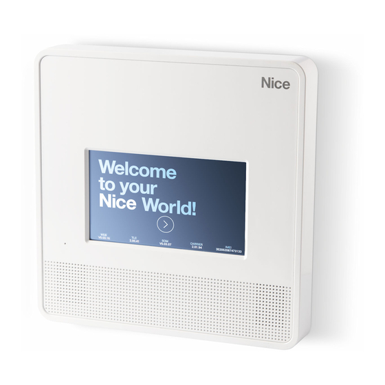
Summary of Contents for Nice MNCUT
- Page 1 Nice MNCUT MNCUTC MNCUC MyNice control unit EN - Instructions and warnings for installation and use...
- Page 3 Grade 2 minimum autonomy for and disposal systems in use in your part of the product other than those to direct purchasers of the Nice power shortage at 12 hours: it must area for this category of products. described in this manual: they may S.p.A.
-
Page 4: Description Of The Control Unit
3 control unit models to choose from. Optional modules MNCUT MyNice control unit 99 zones in 6 areas, dual band two- MNGSM Plug-in GSM module way radio with 7" colour touch screen. Comes with 110–240 VAC MNPSTN Plug-in PSTN module power supply and 6 V 1.2 Ah back-up battery. -
Page 5: Technical Characteristics
3 control unit models and the relative batteries. For each sys- tem the following elements must be calculated: Warning! Control units with touch screen (MNCUT/MNCUTC): take into account the indicated consumption differences, linked to the a) the maximum current draw, calculated by adding to the con- brightness of the touch screen –... -
Page 6: Designing The System
“Technical specifications”. filling in the details, you will have all the elements required The product must be integrated exclusively with two-way My- Nice devices. to complete the successive programming phase. Positioning the devices in the system Design the floor plan of the rooms to be protected and indicate on The control unit incorporates an efficient siren. - Page 7 Subdivision into environments and areas Subdivision into environments and rooms Subdivision of the environment into “areas” Write the name of the rooms on the building’s floor plan. For exam- During the programming phase, the detectors can be grouped into ple: kitchen, living room, stairway, entrance, garage, basement, bed- 6 different AREAS: 1, 2, 3, 4, 5, 6 (the names of the areas can be room, Antonio’s bedroom.
- Page 8 Programming Since the system components communicate MNCUT and MNCUTC touch screen control units After connecting the power cable the touch screen displays the pro- via radio, it is advisable to first configure the gramming procedure. If the screen enters the stand-by mode it can system on a bench before definitively install- be reactivated by simply touching any point.
- Page 9 Ø5 mm Ø5 mm...
-
Page 10: Gsm Connection
GSM connection Installing the MNGSM module Requesting information and sending commands via SMS Insert the SIM card into any telephone, verify that it is active and dis- able the PIN code. Make sure that the control unit is powered, con- Warning! Not envisaged in the EN 501316.1.1.1 standard. -
Page 11: Pstn Connection
PSTN connection Installing the PSTN module Operations Description Make sure that the control unit is not powered and insert the plug-in Ambient listening and speakerphone dialogue module to connect the telephone line (Fig. 4). Connect the control unit to the telephone line (Fig. 5). Verification of the control unit’s ON/OFF status (enabled/dis- abled) Configuration... -
Page 12: Electrical Connections
Electrical connections Warnings The connection to the mains power supply must be done by an ex- • To ensure conformity to the EN 50131 standard, conventional de- pert and qualified electrician in accordance with the regulations on tectors connected directly to the control unit must be certified EN electrical circuits. -
Page 14: Control Units
Elements of the MyNice system Control units MNCUT MyNice control unit 99 zones in 6 areas, dual band two-way radio with 7" colour touch screen. Features 230 V power supply with 6 V 1.2 Ah back-up battery. Inclusive of Wi-Fi module. - Page 15 MNDTAA PIR+MCW dual-technology volumetric detector, 12 m range 90°, with anti-mask- ing function, two-way dual band radio. MNDTPETAA PIR+MCW dual-technology pet-immune detector, 12 m range 90° (lens with fan-shaped coverage), with anti-masking function, two-way dual band radio. MNGB Glass breakage microphone detector, two-way dual band radio, with integrated mag- netic contact.
-
Page 16: Device Configuration
Device configuration Parameters common to all break-in detectors Relevant area: the break-in detectors can be inserted in one or Interactive configurations (AND): this function pairs two sensors more areas (set of devices). or an area, signals the break-in alarm if both sensors or at least two sensors in the area detect a break-in within a pre-set time between Type of alarm: the various alarms generated by the device can be 10 and 180 seconds. -
Page 17: User Functions
Control unit parameter configuration Enabling prevention with open doors/windows: (normally ena- Enable duress function from touch screen: the duress function bled in accordance with EN 50131). If any doors/windows are open, allows – by entering a specific PIN – for simulating the alarm system’s this function prevents the alarm from enabling until all the door/win- disabling with the discrete sending of calls or alarm alerts to enabled dows protected with MNMC have been closed. -
Page 18: Installer Menu
To test the devices (field meter, device tests, combiner test, siren test, frame test System Test and relay test) Programming your domotics To pair Nice automations devices Scenarios To create, modify and set timer for scenarios System saving via MicroUSB, resetting of the system via MicroUSB, updating of... - Page 19 How to connect IP video cameras Up to 4 IP video cameras can be connected to the control unit, through the domestic Wi-Fi network (only control units connected in Client mode). Access the Device programming menu - IP video cameras Enter the user name and password of the IP video camera, the AD- DRESS LINK and the MAC ADDRESS then set the reception interval of the frames from 1 to 5 seconds and the number of frames...
- Page 20 Nice S.p.A. Via Pezza Alta, 13 31046 Oderzo TV Italy www.niceforyou.com info@niceforyou.com...


Need help?
Do you have a question about the MNCUT and is the answer not in the manual?
Questions and answers