Nice MC824L Instructions And Warnings For Installation And Use
Hide thumbs
Also See for MC824L:
- Quick manual (2 pages) ,
- Instructions and warnings for installation and use (89 pages)
Table of Contents
Advertisement
Quick Links
Advertisement
Table of Contents

Related Manuals for Nice MC824L


Summary of Contents for Nice MC824L
- Page 1 Nice MC824L Control unit EN - Instructions and warnings for installation and use...
-
Page 2: Table Of Contents
ENGLISH GENERAL SAFETY WARNINGS AND PRECAUTIONS Translation of the original instructions in full GENERAL SAFETY WARNINGS AND PRECAUTIONS WARNING! Important safety instructions. Observe all the instructions as improper installation may cause serious damages. CONTENTS WARNING! Important safety instructions. It is important to comply with these instructions to GENERAL SAFETY WARNINGS AND PRECAUTIONS . -
Page 3: Product Description And Intended Use
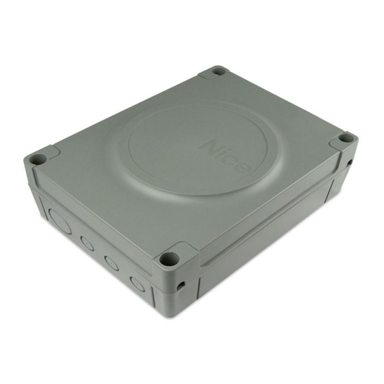
PRODUCT DESCRIPTION AND INTENDED USE MC824L is an electronic control unit for automating swing gates. MC824L is able to command electromechanical actuators of the PRODUCT DESCRIPTION AND INTENDED USE type indicated in “Table 4”. It incorporates a system that verifies the force of the motors connected to it (amperometric function). -
Page 4: Installation
3.4 TYPICAL INSTALLATION INSTALLATION “Figure 3” shows an example of an automation system constructed using Nice components. INSTALLATION 3.1 PRE-INSTALLATION CHECKS Before proceeding with the product’s installation, it is necessary – check the integrity of the supply – check that all the materials are in good working order and suited to the intended use –... -
Page 5: Installing The Control Unit
TECHNICAL SPECIFICATIONS OF ELECTRICAL CABLES Identification Cable characteristics KEY SELECTOR cable 2 cables 2 x 0.5 mm Maximum length 50 m [note 3] MOTOR POWER SUPPLY cable 1 cable 3 x 1.5 mm Maximum length 10 m [note 4] ELECTRIC LOCK CONNECTION cable 1 cable 2 x 1 mm Maximum length 10 m Note 1 If the power supply cable is longer than 30 m, a cable... -
Page 6: Electrical Connections
Nice “Bluebus” system. For the other connections, refer to that in sight of the automation. If located in a concealed specified below. -
Page 7: Description Of Connections
4.2.2 Description of connections The meaning of the codes/wording stamped on the electronic board near the relative terminals is described below. Table 2 ELECTRICAL CONNECTIONS Terminals Function Description Cable type Motor 1 Connection of motor M1 [note 1] 3 x 1.5 mm Motor 2 Connection of motor M2 3 x 1.5 mm... -
Page 8: Connecting Other Devices To The Control Unit
4.3 CONNECTING OTHER DEVICES TO THE PHOTOCELL ADDRESSES CONTROL UNIT Position of the Photocell jumpers If the user needs to power external devices, such as a proximity FOTO 2 (PHOTO 2) reader for transponder cards or the light of the key selector Internal photocell triggered during the switch, power can be tapped as shown in the figure. -
Page 9: Motor Selector
4.8 LEARNING OF THE MECHANICAL STOP POSITIONS Once the connected devices have been learned, the mechanical stop positions must be learned (maximum opening and maximum closing). This procedure can be carried out in three Bluebus Stop Open Close different ways: automatic, manual and mixed. In automatic mode, the control unit learns the mechanical stops, 1 2 3 4 5 6 7 8 9 10 11 12 calculates the most appropriate gate leaf offsets and calculates... -
Page 10: Learning In Automatic Mode
4.8.1 Learning in automatic mode 4.8.2 Learning in manual mode To effect the automatic learning procedure: When LEDs "L1..L6" flash, to shift between LEDs simultaneously press and hold the and buttons simply press the button briefly (the LED will flash to signal the current position). release the buttons when LEDs “L3”... -
Page 11: Learning In Mixed Mode
LED “L5” flashes: position 1 of M1 4.8.3 Learning in mixed mode – to command and move motor 2 to position “1” (“Figure 14”): press and hold the button. Once the position is reached, release the button to stop the manoeuvre –... -
Page 12: Checking The Gate Movement
5.1 TESTING For all the above-mentioned documentation, Nice – The sequence of steps to be performed when running the through its technical assistance service – provides testing phase, as described below, refers to a typical system the following: pre-completed forms. -
Page 13: Programming
6.1 USING THE PROGRAMMING BUTTONS PROGRAMMING Button for commanding the gate opening Selection button during the programming phase. There are 3 buttons on the control unit: PROGRAMMING (“Figure 19”) which can be used both to command the control unit during the testing phase and to programme the Button used to stop a manoeuvre available functions. -
Page 14: Level 2 Programming (Adjustable Parameters)
LEVEL 1 FUNCTIONS (ON-OFF) Function Description Function ENABLED: 1 minute after the manoeuvre is completed, the control unit will turn off the “Bluebus” output (connected devices) and all the LEDs, with the exception of the Bluebus LED, which will flash at a slower speed. - Page 15 LEVEL 2 FUNCTIONS (ADJUSTABLE PARAMETERS) Entry Parameter Set value Description (level) Open - Stop - Close - Stop Open - Stop - Close - Open Open - Close - Open - Close CONDOMINIUM During the opening manoeuvre, the “Step-by-Step” and “Open”...
-
Page 16: Special Functions
LEVEL 2 FUNCTIONS (ADJUSTABLE PARAMETERS) Entry Parameter Set value Description (level) 1000 Adjusts the number of manoeuvres 1500 after which the automation 2500 Maintenance maintenance request is triggered notification 5000 (see the ““Maintenance notice” 10000 function” paragraph). 15000 20000 Result of 1 manoeuvre (most recent) Result of 2 manoeuvre... -
Page 17: Troubleshooting Guide
TROUBLESHOOTING... (troubleshooting guide) Some devices are configured for signalling the operating status or the presence of any anomalies. TROUBLESHOOTING GUIDE 7.1 SIGNALLING THROUGH WARNING LIGHT If a warning light is connected to the FLASH output (A) on the control unit, the light will flash once every 1 second while the manoeuvre is being performed. -
Page 18: Signals On The Control Unit
7.2 SIGNALS ON THE CONTROL UNIT The control unit has LEDs “L1-L8” on the buttons and LEDs “L9- L13” on the control unit terminals (“Figure 22”). Each of these LEDs can emit special signals both during normal Bluebus Stop Open Close operation and in case on anomalies. -
Page 19: Anomaly Log
Table 11 SIGNALS OF LED (L1..L4) (“FIGURE 22”) Status Meaning Possible solution LEDs L1 - L2 Change in the number of It is necessary to run the device learning procedure (refer to the “Learning devices connected to the Slow flashing of connected devices”... -
Page 20: Connecting The Ibt4N Interface
“Table 12” and “Table 13” show the “Receiver outputs” and the 8.2 CONNECTING THE IBT4N INTERFACE “Control unit inputs” associated with each. The control unit is equipped with a “IBT4N”-type connector for the IBT4N interface, which allows for connecting all devices Table 12 equipped with BusT4 interface, such as, for example, Oview SMXI / SMXIS OR OXI / OXIFM / OXIT / OXITFM IN MODE 1 OR MODE... -
Page 21: Connecting The Ps324 Back-Up Battery
8.3 CONNECTING THE PS324 BACK-UP BATTERY PRODUCT MAINTENANCE The control unit is configured for being powered with PS324 back-up batteries that intervene in case of a power outage. Being an electronic part, the control unit does not require PRODUCT MAINTENANCE Before installing a back-up battery, disconnect the any special maintenance. -
Page 22: Technical Specifications
TECHNICAL SPECIFICATIONS TECHNICAL SPECIFICATIONS All technical specifications stated in this section refer to an ambient temperature of 20°C (± 5°C). Nice S.p.A. reserves the right to apply modifications to the product at any time when deemed necessary, without altering its functions and intended use. -
Page 23: Conformity
“partly completed machinery” Note - The contents of this declaration correspond to declarations in the official document deposited at the registered offices of Nice S.p.a. and in particular to the last revision available before printing this manual. The text herein has been re-edited for editorial purposes. A copy of the original declaration can be requested from Nice S.p.a. (TV) I. - Page 24 NOTES 24 – ENGLISH...
-
Page 25: Instructions And Warnings For The User
INSTRUCTIONS AND WARNINGS FOR THE USER Before using the automation for the first time, ask the installer to Safety devices out of order: the automation can also be used explain the origin of any residual risks and take a few minutes when one or more safety devices are defective or out of order. - Page 26 NOTES 26 – ENGLISH...
- Page 27 NOTES ENGLISH – 27...
- Page 28 Nice SpA Via Callalta, 1 31046 Oderzo TV Italy www.niceforyou.com info@niceforyou.com...
Need help?
Do you have a question about the MC824L and is the answer not in the manual?
Questions and answers