
Related Manuals for Expolite LED FRESNEL 2K


Summary of Contents for Expolite LED FRESNEL 2K
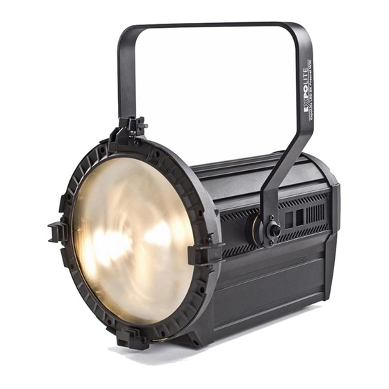
- Page 1 LED FRESNEL 2K BEDIENUNGSANLEITUNG FÜR LED22930 LED FRESNEL 2K USER MANUAL FOR LED22930...
-
Page 2: Technische Daten
PRODUKTEIGENSCHAFTEN TECHNISCHE DATEN Spannung 100-240V AC @ 50/60Hz Leistungsaufnahme 340 Watt 32 x 10 W Cree WW Led Array (3100 K) Zoom 18° - 60° Farbwiedergabe <85 RaMax Lichtfluss ~ 8.500 lmMax. Intensität ~ 81.500 cd Betriebstemperatur 0° - 40° C Gehäuse Aluminium Druckguss/Kunststoff Schutzklasse... - Page 3 SICHERHEITSHINWEISE LESEN SIE VOR DER INBETRIEBNAHME IMMER DIE BEDIENUNGS- ANLEITUNG. STELLEN SIE SICHER, DASS DER AM GERÄT ANGEGE- BENE WERT FÜR DIE NETZSPANNUNG DEM DER VERSORGUNGS- SPANNUNG VOR ORT ENTSPRICHT. Dieses Produkt darf nur von qualifiziertem Fachpersonal installiert werden. Arbeiten am Gerät dürfen nur von qualifizierten Servicekräften vorgenommen werden.
- Page 4 SCHUTZ GEGEN FREMDKÖRPER UND WASSER Für Geräte mit Schutz gegen Fremdkörper und Wasser nach IP-Code Die Schutzart eines Gerätes wird anhand genormter Prüfverfahren festgestellt. Zur Einordnung der Schutzart wird der IP-Code be- nutzt. Dieser setzt sich aus den Buchstaben IP und zwei Kennzif- fern zusammen.
- Page 5 TEMPORÄRER BETRIEB Grundsätzlich ist Veranstaltungsequipment immer für den vorübergehenden Einsatz konzipiert, der einer repräsentativen Anwendung für Eventbeleuchtung entspricht. Hierzu zählen Kon- zerte, Festivals, Einsätze in Spielstätten wie Theatern, Clubs und Diskotheken oder vergleichbare Venues. Ein Dauerbetrieb, besonders unter Außenbedingungen oder eine dauerhafte bauliche Anbringung im Außenbereich kann zu Einschränkungen in der Funktion sowie vorzeitiger Ermüdung der Dichtungen, Kabel und Oberflächenbeschichtung führen.
-
Page 6: Installation
INSTALLATION BEFESTIGUNG HÄNGEND: Das Gerät kann an dem Haltebügel hängend montiert werden. Hierzu muss eine geeignete Befestigung wie eine Traversenschelle benutzt werden. Bitte achten Sie auf geltende Vorschriften zur Sicherung wie das Anschlagen eines Sicherungsseiles. HINWEIS! Das LED-Modul kann in jeder beliebigen Position montiert werden. Die Neigung im Bügel kann bequem durch lösen der Arretierungs- schraube verstellt werden. -
Page 7: Bedienung
DISPLAYMENÜ BEDIENUNG Menu: Weiter zum nächsten Menü. Enter: Auswahl des aktuellen Punktes. Down: Scrollen durch das Menü oder senken von Werten Scrollen durch das Menü oder erhöhen von Werten. DIM: Durch Doppelklick auf die Tast-Potis schaltet das Gerät in den Statik-Mode. Zoom: Klicken und anschließendes Drehen, wird der Dimmer oder Zoom eingestellt. - Page 8 ZOOM BASE POS1 POS2 PERF LIVE STDO POWER MCON SELF MAST CAL2 POS1 (0-255) POS2 STATISCHER BETRIEB HINWEIS! Wenn das Gerät auf den Modus Master geschaltet ist, werden die statischen Einstellungen automatisch an alle gleichen Geräte die durch eine Datenverbindung verbunden sind weitergegeben. Wenn das Gerät DMX-Daten empfängt wechselt es nach 2 Minuten zurück in das Hauptmenü.
- Page 9 GERÄTEEINSTELLUNGEN SET: In diesem Menü sind Zusatzfunktionen hinterlegt UPLD: Übertragen von Benutzerprogrammen auf Slave-Gerät REST: Reset COLR: Farbkalibrierung DIM1, DIM2, DIM3 oder DIM4 Dimmergeschwindigkeiten für Halo- gensimulation (DIM4 = langsam) DERR: DMX-Fehlerverhalten. Letztes Signal beibehalten oder abdimmen. ZOOM: Festlegen der Start- und Endposition des Zooms. CURV: Einstellen der Dimmerkurve MENÜ...
- Page 10 ZOOMBEGRENZUNG Im Menü ZOOM werden die Endpunkte des Zoomweges definiert, der über DMX abrufbar ist. MENÜ CAL2 POS1 (0-255) POS2...
- Page 11 STEUERUNG MIT DMX512 KONTROLLER KANALBELEGUNG Dieses Produkt hat verschiedene DMX-Modi (siehe Personality) DMX KANAL WERT FUNKTION 0ó255 DIMMER DMX KANAL WERT FUNKTION DIMMER 0ó255 0ó255 FINE DIMMER STD.P DMX KANAL WERT FUNKTION DIMMER 0ó255 0ó255 FINE DIMMER 0ó9 NO STROBE 10ó99 STROBE (SLOW TO FAST) 100ó109...
- Page 12 ANHANG EXPLOSIONSZEICHNUNG TEILE TEILE magnetic stopper sensor lens hood tilt belt shade leaf buckle back cover fresnel lens rear plate 5 degree frosted flakes fuse head front cover control board head pull aluminium driver board hanging bracket adaptor PCB long tooth transmission PS socket (male) rod assembly PS socket (female)
-
Page 13: Product Specifications
PRODUCT SPECIFICATIONS TECHNICAL SPECIFICATION voltage 100-240V AC @ 50/60Hz power consumption 340 Watt 32 x 10 W Cree WW Led Array (3100 K) zoom 18° - 60° colour rendering <85 RaMax light flow ~ 8.500 lmMax. intensity ~ 81.500 cd operation temperature 0°... -
Page 14: Safety Warning
SAFETY WARNING This product must be installed by a qualified professional. All maintenance must be carried out by a qualified electrician. A minimum distance of 0.5 m must be maintained between the equipment and a combustible surface. The product must always be operated in a well ventilated area. DO NOT stare directly into the LED light source. - Page 15 PROTECTION AGAINST SOLIDS AND WATER Only for IP-rated fixtures The protection level of a housing is set by apllied standards. For classification there is used the IP-Code. It contains the declaration „IP“ and two following numbers. The first number charaterises the protection against harmful effects of solids, the second is rating the waterprotection.
- Page 16 TEMPORARY USE Eventequipment is designed for temporary use. This are typical purpose as concerts, festivals, theatre, clubs and disco use and referable venues. Longterm use, specially under outdoorconditions and fixed out- door installation can bring damage in aging materials and affect the coated surface.
- Page 17 INSTALLATION MOUNTING HANGING: The LED fixture can be mounted in a hanging position using the supporting bracket. The bracket should be secured to the mounting truss or structure using a standard mounting clamp. Please note that when hanging the unit a safety cable should also be used.
-
Page 18: Display Panel Operation
DISPLAY PANEL OPERATION DISPLAY OPERATION Menu: back Enter: enter Down: down DIM: doubleclick to access Zoom: doubleclick to access QUICK-ACCESS KEYS MENU By press and holding the MENU key when at the main menu it is possible to directly access the DIM function. MENU MAP MENU STAT... - Page 19 DIMMER (STAT) DIM: to adjust level of intensity ZOOM: to adjust the zoom position MENU STAT 0-100 ZOOM 0-100 NOTE! When using this function, if the MCON menu is set as MAST, then the fixture will transfer the DIM values to other fixtures. When DMX data is received at the fixture, it will automatically return to main menu after 2 minutes of no key operation.
- Page 20 GERÄTEEINSTELLUNGEN SET: this menu allows the user to adjust key operation settings for this fixture. KEY: select ON for automatic lock-out. Password to re-enter the display is <UP> + <DOWN> + <UP> + <DOWN>. Select DIM1, DIM2, DIM3 or DIM4 for different dimming speeds. (DIM4is the slowest dimming speed) CURV allows the user to adjust the shape of the dimming curve.
- Page 21 DIMMERKURVE 1: OFF 2: CV1 3: CV3 4: CV4 ZOOM CALIBRATION (CAL) Select the ZOOM range POS1 & POS2 set the small position for the zoom function. Note that when using DMX to control the fixture, the user will only be able to access up to the set ZOOM position.It is not possible to adjust beyond the set position.
-
Page 22: Using Dmx512 Controller
USING DMX512 CONTROLLER CHANNEL ASSIGNMENT This product have four DMX512 channel configuration. DMX CHANNEL VALUE FUNCTION 0ó255 DIMMER DMX CHANNEL VALUE FUNCTION DIMMER 0ó255 0ó255 FINE DIMMER STD.P DMX CHANNEL VALUE FUNCTION DIMMER 0ó255 0ó255 FINE DIMMER 0ó9 NO STROBE 10ó99 STROBE (SLOW TO FAST) 100ó109... -
Page 23: Maintenance
APPENDIX MAINTENANCE ITEM ITEM magnetic stopper sensor lens hood tilt belt shade leaf buckle back cover fresnel lens rear plate 5 degree frosted flakes fuse head front cover control board head pull aluminium driver board hanging bracket adaptor PCB long tooth transmission PS socket (male) rod assembly PS socket (female) - Page 24 WWW.EXPOLITE-LED.DE...
Need help?
Do you have a question about the LED FRESNEL 2K and is the answer not in the manual?
Questions and answers