Table of Contents
Advertisement
Quick Links
Advertisement
Table of Contents

Subscribe to Our Youtube Channel
Related Manuals for 4IPNET EAP701


Summary of Contents for 4IPNET EAP701
- Page 1 EAP701 V1.00 Enterprise Access Point...
-
Page 2: Copyright Notice
4IPNET, INC. You may not alter or remove any copyright or other notice from copies of the content. All other brand and product names are claimed or registered marks of their respective companies or organizations. -
Page 3: Fcc Caution
Any changes or modifications not expressly approved by the party responsible for compliance could void the user's authority to operate this equipment. This transmitter must not be co-located or operating in conjunction with any other antenna or transmitter. Copyright © 4IPNET, INC. All rights reserved. - Page 4 This declaration is only valid for configurations (combinations of software, firmware, and hardware) provided and supported by 4ipnet Inc. The use of software or firmware not provided and supported by 4ipnet Inc. may result in the equipment no longer being compliant with the regulatory requirements.
-
Page 5: Package Contents
EAP701 Enterprise Access Point ENGLISH Preface Package Contents The 4ipnet EAP701 Wall Jack Access Point is an 1. 4ipnet EAP701 x 1 in/on-the-wall as well as a ceiling-mounted Wi-Fi 2. Quick Installation Guide (QIG) x 1 IEEE 802.11b/g/n 2.4GHz 2 X 2 MIMO access point, 3. -
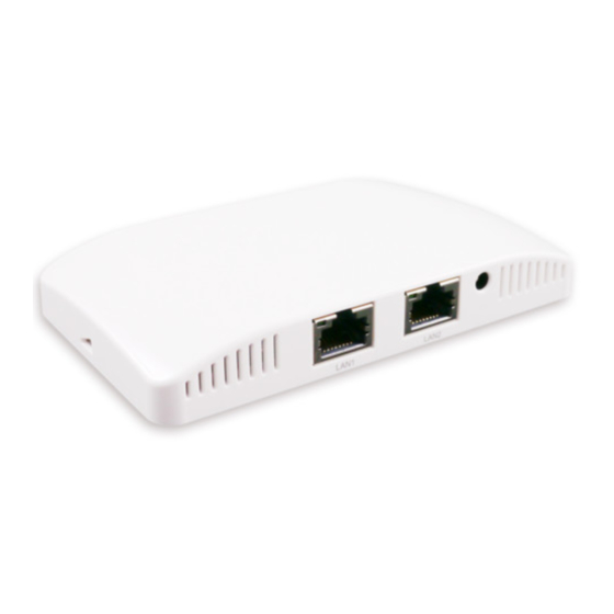
Page 6: System Overview
2 LED Indicators 4 LED lights. Representation is listed at the top of the panel. 3 WES Button WDS Easy Setup. Press the button to build up a WDS link with another peer. Copyright © 4IPNET, INC. All rights reserved. - Page 7 1 110 Punchdown Block Copper wire punch down for in-wall application 2 Uplink (PoE) Port For Uplink connection. This port can be used to connect to a controller, gateway, or directly to the internet. PoE is supported. Copyright © 4IPNET, INC. All rights reserved.
-
Page 8: Hardware Installation
Please follow the steps mentioned below to install the hardware of EAP701: Step 1. Place the EAP701 at the best location. The best location is usually at the center of your intended wireless network. The EAP701 supports two types of mounting;... - Page 9 The Uplink port is capable of receiving PoE. Connect an IEEE 802.3af-compliant PSE device (e.g. a PoE-switch) to the Uplink port of EAP701 with the Ethernet cable. c) Use a standard 110 punchdown tool to punch copper wires onto the punchdown block (pin assignment 568A) Step 4.
- Page 10 Now, the Hardware Installation is complete. Punch down tools may vary by country. Please contact the 4ipnet Support Team for recommendations if needed. Please use only the power adapter supplied with the package. Using a different power adapter may damage this system.
-
Page 11: Getting Started
1. To access the Web Management Interface, connect the administrator PC to the LAN port of EAP701 via an Ethernet cable. Then, set a static IP address on the same subnet mask as EAP701 in TCP/IP of your PC, such as the following example: IP Address: 192.168.1.100... - Page 12 EAP701 Enterprise Access Point ENGLISH 4. After a successful login to EAP701, a System Overview page of the Web Management Interface will appear, as depicted below. The Radio Status and AP Status will be shown. The Web Management Interface - System Overview Page 5.
-
Page 13: Common Settings
Enter the old password and then a new password with a length of up to 32 characters, and retype it in the Re-enter New Password field. Click SAVE to save the changes. Copyright © 4IPNET, INC. All rights reserved. - Page 14 Select the RF card you would like to set up. Determine the Band and Channel settings: Select your preferred Band and Channel for you wireless connection. For example, select 802.11g+802.11n for the band and 6 for the channel. Copyright © 4IPNET, INC. All rights reserved.
- Page 15 Step 3. Configure VAP (Virtual Access Point) Profile Settings VAP Configuration Page (VAP-1 shown) The EAP701 supports up to 8 virtual APs (VAPs). Configure VAP profile settings: (a) Select the VAP Configuration tab to configure the settings of the desired VAP.
- Page 16 Virtual AP Overview Page Step 4. Configure WDS (Wireless Distribution System) Settings (Optional) To extend the wireless coverage, EAP701 supports up to 4 WDS links for connecting wirelessly to other WDS-capable APs, or peer APs. By default, all WDS profiles are disabled.
- Page 17 (a) Enable WDS. (b) Enter the MAC Address (peer AP) and then Click SAVE. If you are using another EAP701 as the peer AP, simply repeat the above-mentioned steps to configure another peer AP(s). On each and every configuration page, you may click SAVE to save the changes of your configured settings, but you must reboot the system for the changes to take effect.
Need help?
Do you have a question about the EAP701 and is the answer not in the manual?
Questions and answers