
Related Manuals for Duplo DSF-2000


Summary of Contents for Duplo DSF-2000
-
Page 1: Maintenance Manual
Duplo DSF-2000 Sheet Feeder Maintenance Manual Provided By http://www.MyBinding.com http://www.MyBindingBlog.com... -
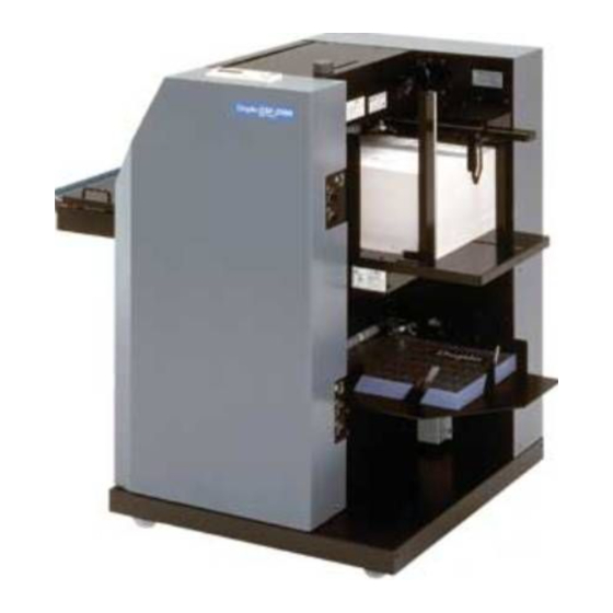
Page 2: Sheet Feeder
SHEET FEEDER DSF-2000 MAINTENANCE MANUAL... -
Page 3: Table Of Contents
TABLE OF CONTENTS CHAPTER 1 MECHANISM 1. Outline of Mechanism of This Machine ... 1-2 2. Paper Feed Mechanism ........1-5 3. Paper Feeder A ..........1-9 4. Paper Feeder B ..........1-13 5. Reversal Section ..........1-15 6. Conveyance Bridge Section ......1-19 7. - Page 4 CHAPTER 1 MECHANISM 1. Outline of Mechanism of This Machine ... 1-2 6. Conveyance Bridge Section ......1-19 1-1. Operations of Machine during Count 6-1. Replacing the Paper Ejection Sensor Processing Mode and When Using and Microswitch ........1-19 End Mark (Count Mode) ......1-2 6-2.
-
Page 5: Outline Of Mechanism Of This Machine
1. OUTLINE OF MECHANISM OF THIS MACHINE 1-1. Operations of Machine during Count Processing Mode and When Using End Mark (Count Mode) (1) Perform the required settings for count processing or using the end mark on the control panel. (2) Memorize the characteristics of the paper in the machine by test feeding the paper. (3) Press the start button to start operations. -
Page 6: Positions Of Main Parts
1-3. Positions of Main Parts Control panel Frame F Paper feed clutch Gate solenoid Reversal clutch 1 Reversal counter Reversal clutch 2 Paper feed clutch Remote board Power board Operating side 99T-M12M0-0107-0... - Page 7 Paper feed tray A up/down motor Frame B Upper limit switch A Index sensor for end mark Upper door switch Suction fan Double-feed detection sensor Suction solenoid Separator fan Conveyance motor Paper ejection sensor Lower limit Reversal sensor switch unit A (light-receiving side) (Black cover) Paper feed tray B...
-
Page 8: Paper Feed Mechanism
2. PAPER FEED MECHANISM 2-1. Outline of Paper Feed Mechanism (1) Press the start button to operate the machine. With the paper feed tray’s up and down mechanism, the paper on the paper feed tray rises up to the position detected by the level sensor. (2) Then the paper feed tray goes down to a certain position and stops. -
Page 9: Suction Conveyance Section
2-2. Suction Conveyance Section The suction conveyance section consists of the DC fan suction belt, suction box, conveyance shaft, and electromagnetic clutch to rotate the conveyance shaft. The DC fan is the suction source to suck the paper. Frame B When the DC fan starts to operate, the suction box is in a suction state. -
Page 10: Solenoid Valve
2-3. Solenoid Valve The valve is used to switch the suction box to the Bottom of suction box Valve head suction/release state. Use the DC solenoid to switch the suction/release state. Lever A large square hole is on the bottom of the suction Solenoid base box. -
Page 11: Separator
2-5. Separator When the sheets of paper are double-fed with the suction belt, the separator keeps the top second or more sheets of paper from being fed. Separator air box The separator moves up and down against the suction belt. Therefore adjust the space between the tip end of the separator and the surface of the suction belt. -
Page 12: Paper Feeder A
3. PAPER FEEDER A Conveyance shaft Sensor cover Sensor cover T mark sensor ass’y Paper feed inlet A upper Paper feed inlet A lower Upper door Paper feed section secondary conveyance roller Reinforcement A lower 99T-M12M0-0107-0... -
Page 13: Detection Of No-Paper
3-1. Detection of No-paper Whether there is the paper on the paper feed tray or not is detected. The light-receiving sensor board is mounted to the bracket of the suction conveyance section together with the sensor plate. (Same sensor board as the paper feeder B) To replace it, remove the suction conveyance section. -
Page 14: Side Guide A
3-2. Side Guide A Guide to hold paper on the paper feed tray to prevent the paper from shifting to the operating side. As the racks at the top and bottom are engaged with the top and bottom gears of the moving shaft, they move parallelly. -
Page 15: Paper Feed Tray Up And Down Section
3-3. Paper Feed Tray Up and Down Section The paper feed tray is raised and lowered by the rotation of the sprocket of the up/down shaft and the pulling of the paper feed tray by the chain. The other chain is a spring which pulls the paper feed tray in the rising direction at all times. -
Page 16: Paper Feeder B
4. PAPER FEEDER B Suction conveyance section Paper feed section secondary conveyance roller Lower door Bracket Sensor stay Reversal auxiliary guide 4-1. Detection of No-paper Whether there is the paper on the paper feed tray or not is detected. The light-receiving sensor board is mounted to the bracket of the suction conveyance section together with the sensor plate. -
Page 17: Greasing The Secondary Conveyance Roller Of The Paper Feed Section
4-3. Greasing the Secondary Conveyance Roller of the Paper Feed Section This roller is pre-greased. When the grease runs out, a whistle-like buzzer is sounded. The fixing screw of the bracket to which the secondary conveyance roller is attached can be seen when the lower door and reversal auxiliary guide are removed. -
Page 18: Reversal Section
5. REVERSAL SECTION Gate Reversal Solenoid counter Stopper Reversal sensors Reversal roller 1 Reversal roller 2 Reversal auxiliary guide 1-15 99T-M12M0-0107-0... -
Page 19: Mechanism
5-1. Mechanism Mechanism which turns paper fed from the paper feeder A inside out when ejecting. (1) Select the reversal mode and start the machine. The reversal switching gate is switched by the solenoid. (2) The two clutches operate together so that reversal roller shaft 1 and reversal roller shaft 2 rotate in the direction to send the paper downwards. -
Page 20: Replacing The Clutch
5-2. Replacing the Clutch Clutches A and B of the reversal section need to be replaced about a million times of reversals. To replace, remove the bracket, rotating stopper A, transmission shaft gear, collar B, key B, clutch B, reversal shaft gear, and clutch A (collar A, field core, key A, rotor, gear). -
Page 21: Adjusting The Gate Solenoid And Stopper
5-3. Adjusting the Gate Solenoid and Stopper Perform the adjustment while checking the gate through the peeping hole at the frame F side. Adjustment of solenoid ON state Adjust the attaching position of the solenoid so that the clearance between the tip of the gate and upper side of the guide plate (upper) becomes 0.5 to 1.5 mm (0.02"... -
Page 22: Conveyance Bridge Section
6. CONVEYANCE BRIDGE SECTION Sends paper ejected from inside the machine to the downstream processing unit. The guide angle of the ejection section can be finely adjusted. Rubber plate Bridge cover F Door cover Secondary conveyance rollers Stopper Microswitch Paper ejection sensor Magnet catcher 6-1. -
Page 23: Upper Door Section
7. UPPER DOOR SECTION Upper door Stay Parallel to tilted surface of frame Adjusting angle Secondary conveyance rollers Switch cover Pillar M6 washer × 3 Limiter Pillar E ring Fulcrum plate Frame B Frame F 7-1. Removing Procedure (1) Remove the left and right limiters, remove the E ring of the pillar at the frame B side, and remove the washer. (2) Remove the plate from the frame F side, and pull the pillar to remove the upper door. -
Page 24: Lower Door Section
8. LOWER DOOR SECTION Lower door Conveyance guide Secondary bearings Limit bracket Washers Z collars Frame B Plate Fulcrum shaft E rings Frame F 8-1. Removing Procedure (1) Remove the left and right limit brackets. (2) Remove the E ring which can be seen from the frame B side, and remove the plate. (3) Move the fulcrum shaft slightly to the frame B side to remove the lower door. -
Page 25: End Mark Detection Section
9. END MARK DETECTION SECTION 9-1. Outline Detects the pre-entered end mark position with the reflection type sensor. Detects at the appropriate timing at the index disc at the frame B side after the front edge of the paper reaches the sensor. -
Page 26: Replacing The End Mark Sensor
9-2. Replacing the End Mark Sensor To replace the top sensor, remove the sensor cover, and remove the T mark sensor ass’y. To attach, press part a of the T mark sensor ass’y shown in the figure against the paper feed inlet A upper, and secure it. -
Page 27: Adjusting The Light-Emitting Volume Of
9-3. Adjusting the Light-emitting Volume of the End Mark Sensor (Maintenance Menu) If the end mark sensor or MC unit has been replaced, the light-emitting volume must be adjusted in the maintenance menu. Place a 52.3 g/m paper in the conveyance route of the end mark sensor detection section, and adjust the light- emitting volume (LED setting value) so that both the PD1 and PD2 values are between 110 and 120. -
Page 28: Double-Feed Detection Section
10. DOUBLE-FEED DETECTION SECTION 10-1. Adjusting the Light-emitting Volume in Use of Thick Paper and Thin Paper (Maintenance Menu) To adjust the light-emitting volume of the LED when using thin paper: Adjust so that the light-receiving value is 155 on average for 52.3 g/m paper. -
Page 29: Adjusting The Tension Of The Timing Belt
11. ADJUSTING THE TENSION OF THE TIMING BELT Slack is 3 to 5 mm (0.12" to 0.20") with 300 g loaded 60S3M468 Slack is 6 to 8 mm (0.24" to 0.31") with 100 g loaded 140XL050 Slack is 5 to 7 mm (0.20" to 0.28") with 300 g loaded Frame B 100S3M804... - Page 30 Slack is 2 to 4 mm (0.08" to 0.16") with 100 g loaded 60S3M144 60S3M252 Frame F Tension roller (black) Grease sliding part in contact with shaft 60S3M180 60S3M144 Operating side 1-27 99T-M12M0-0107-0...
-
Page 31: Structure Of Conveyance Rollers And Conveyance Guides
12. STRUCTURE OF CONVEYANCE ROLLERS AND CONVEYANCE GUIDES Conveyance rollers and conveyance guides are arranged as shown in the figure below. Paper feed conveyance roller Secondary conveyance rollers ∗ Suction belt Paper feed section secondary conveyance roller ∗ Conveyance rollers Reversal roller 1 Reversal roller 2 Bridge rollers... -
Page 32: Paper Feed Count Of Paper Feeder A
13. PAPER FEED COUNT OF PAPER FEEDER A The number of paper feeding performed by the paper feeder A is counted by the main board, and can be checked in the maintenance menu. When replacing the board, note down the current count. 1-29 99T-M12M0-0107-0... -
Page 33: Maintenance
14. MAINTENANCE Clean the following parts Conveyance roller, suction belt (Refer to “12. STRUCTURE OF CONVEYANCE ROLLERS AND CONVEYANCE GUIDES”.) Reversal clutch (Refer to “5-2. Replacing the Clutch”.) Following sensors: Double-feed detection sensor (Refer to Non-operating side in “1-3. Positions of Main Parts”.) End mark detection sensor (Refer to “9-4. -
Page 34: Electrical Components
CHAPTER 2 ELECTRICAL COMPONENTS 1. Block Diagram of Structure and Outline of 1-26. LED 2 (Orange) ........2-7 Each Block ............2-2 1-27. Switching Power Supply ......2-7 1-1. MC Unit ..........2-5 1-28. Remote Unit (RM Unit) ......2-7 1-2. -
Page 35: Block Diagram Of Structure And Outline Of Each Block
1. BLOCK DIAGRAM OF STRUCTURE AND OUTLINE OF EACH BLOCK 1-2. OP unit (Control panel) 1-3. MK unit 1-5. Conveyance motor 1-4. End mark sensor (Upper/lower) 1-6. Index sensor 1-7. Paper feed tray A (B) motor 1-16. Upper door, lower door, bridge door switches 1-8. - Page 36 1-22 (A) 1-11 (A) 1-8 (A) 1-7 (A) 1-9 (A) 1-23 (A) 1-14 1-22 (B) 1-7 (B) 1-16 (Lower door) 1-9 (B) 1-23 (B) 1-8 (B) 1-20 (B) 1-10 (A) 1-12 1-17 1-13 (2) (Refer to “3-1.” in CHAPTER 1 MECHANISM.) 1-13 (1) 1-15...
- Page 37 1-21 1-19 1-16 (Upper door) 1-20 (A) 1-18 1-16 (Bridge door) 99T-M12M0-0107-0...
-
Page 38: Mc Unit
1-1. MC Unit The MC unit controls the whole machine by the 8-bit microprocessor. It also incorporates a motor, fan, and solenoid driving circuit. It has a built-in DC converter which generates +5 V with the DC +24 V power supply input. A DC +5 V power supply is used for ICs and sensors while a DC +24 V is used for driving the motor, fan, and solenoid. -
Page 39: Paper Feed Tray A (B) Suction Valve Solenoid
1-11. Paper Feed Tray A (B) Suction Valve Solenoid Solenoid for driving the suction valve. Uses a DC +24 V power. 1-12. Reversal Switching Solenoid Solenoid for driving the reversal switching section. Uses a DC +24 V power. 1-13. Reversal Clutch 1 (2) Electromagnetic clutch for transmitting drive to reverse paper. -
Page 40: Paper Feed Tray A (B) Upper Limit Position Switch
1-22. Paper Feed Tray A (B) Upper Limit Position Switch Normal closed microswitch. When the switch is open, contact is established. This switch detects when the suction conveyance section is pushed up and cuts off the output source of the paper feed tray motor to prevent damage of mechanical parts, etc. -
Page 41: Power Supply Inlet
1-31. Power Supply Inlet Incorporated in the remote unit. Connected to the power cord. 1-32. IF Cable Interface cable for communication with the downstream processing unit. Be sure to use the specified cable. 1-33. Power Cord Supplies primary power to the machine. 99T-M12M0-0107-0... -
Page 42: Errors And Causes
2. ERRORS AND CAUSES 2-1. When Paper Jams Occur The first line of the LCD on the control panel displays “PAPER JAM”. The second line displays “Feed” (paper feed section), “Conveyance” (conveyance section), “Eject” (paper ejection section), or “Turn” (reversal section) according to where the paper has jammed. -
Page 43: Troubleshooting
2-2. Troubleshooting When a problem occurs, the first line of the message on the LCD of the control panel will display “Malfunction”. The second line will display the name of the problem. Details are provided below. Details of problems Display in 2nd Line Description Feed Motor Trouble The conveyance motor is not rotating properly. -
Page 44: Other Condition Messages
2-3. Other Condition Messages The control panel also displays messages of other conditions of the machine such as when a door is opened, etc. The causes of such messages are shown below. In some cases, if the message and actual condition differ such as when “Door open”... -
Page 45: Maintenance Menu
3. MAINTENANCE MENU Display Stop button Start button Power ON indicator Clear Escape button button Jog dial/Enter button Function button 3-1. Entering the Maintenance Menu Press the escape button once on the initial screen of the control panel. Turn the jog dial by three clicks towards the right, and press the clear button once. -
Page 46: Sensor Check Mode
3-4. Sensor Check Mode Turn the jog dial to display “Sensor Check”, and press the jog dial. Turn the jog dial to display the name of the sensor to be checked. The name will be displayed as shown in the following examples. Also can be checked with the buzzer. (Example 1) To check the no-paper detection sensor (photointerrupter) of the paper feed tray B “On”... -
Page 47: Feed Speed Setting
3-9. Feed Speed Setting Turn the jog dial to display “Feed Speed”, and press the jog dial. Turn the jog dial to set the paper feed speed. 3-10. Double-feed Sensor Data Mode This mode can be used to set the light volume when the paper thickness to be detected is set to “Heavy” or “Thin” in double-feed sensor. -
Page 48: Precautions On Replacing The Mc Unit
4. PRECAUTIONS ON REPLACING THE MC UNIT Data memorized by the machine even after the power is turned off is registered in the EEPROM (nonvolatile memory) on the MC unit (board). For this reason, previous data will be lost if the MC unit is replaced. Some of the data memorized may be unique to the machine. -
Page 49: Precautions On Replacing Fuses
5. PRECAUTIONS ON REPLACING FUSES CAUTION : For continued protection against risk of fire, replace only with same type and rating of fuse. Fuse type and rating: UL, IEC127 Fuse T 6.3 A Board display: FUSE 1 2-16 99T-M12M0-0107-0... -
Page 50: Lcd Map
6. LCD MAP 6-1. LCD Map (Normal Menu) NOTE Turning the jog dial switches the display within the same hierarchy, and press to move to the hierarchy below (right side of the LCD map). If no hierarchy exists below, turning the jog dial selects an item or sets a value. Pressing it confirms the selected item or value set. - Page 51 Endmark Set. Sensor1 Set. Sensor1 on/off Sensor1 on/off Off On ∗ Sensor1 Position Sensor1 Position 210 ∗ Sensor2 Set. Sensor2 on/off Sensor2 on/off Off On ∗ Sensor2 Position Sensor2 Position 210 ∗ Mark Mode Count Select Mark Mode None Count Random ∗ Size Detect Mode Size Detect Mode Off On ∗...
- Page 52 Custom Size Custom 1 Size L=364 W=257 Length L= 364 Select Length L= 364 ∗ Width W= 257 Select Width W= 257 ∗ Custom 2 Size L=364 W=257 Length L= 364 Select Length L= 364 ∗ Width W= 257 Select Width W= 257 ∗...
- Page 53 Other Setting Tone Tone on/off On Off ∗ LCD Setting Shift Speed Fast Select Shift Sp. Fast Normal Slow Very Slow ∗ Blink Speed Fast Select Blink Sp. Fast Normal Slow Very Slow ∗ mm/In Setting Meter Select mm/In Meter Inch ∗ Feed Setting Set Speed 30 [set/min]...
- Page 54 A Tray Level 17 [%] Select Level 17 20 25 33 50 ∗ A Tray Position 120 [mm] Select Position 120 130 140 150 160 170 ∗ B Tray Setting B Tray Check Check on/off Off On ∗ B Tray Thick Auto Select Thick Auto Heavy Thin ∗...
- Page 55 Feed Cl. Timing A.- 2 B.- 2 Clutch Timing A Select Timing A 1 2 3 4 5 6 ∗ Clutch Timing B Select Timing B 1 2 3 4 5 6 ∗ No. Of Sets Subtract Select Process Add Subtract ∗ Sheet Jog Sheet Jog Off 1 2 3 4 5 ∗...
-
Page 56: Lcd Map (Maintenance Menu)
6-2. LCD Map (Maintenance Menu) NOTE : In the sensor check mode, the sensor state will be displayed as “On” or “Off”. Maintenance Menu (Initial screen) Select M. Mode ROM Version MC ROM Version xxx-nnnnn TRAY ROM Version xxx-nnnnn OP ROM Version xxx-nnnnn MARK ROM Version xxx-nnnnn... - Page 57 Sensor Check Index On Sensor Check Eject On Sensor Check Size 1 On Sensor Check Size 2 On Sensor Check Upper Door On Sensor Check Lower Door On Sensor Check Bridge Door On Select M. Mode Motor Sol. Test Motor test Feed Motor test A tray...
- Page 58 Option setting None Option select None OPTION1 B Tray Mode B Tray Mode Off On Feed Speed 1350 [mm/sec] Input Speed ∗ Can be set to any value between 120 and 150. 135* Select M. Mode Double Feed Data Double Feed Data LED Heavy Data A.LED–H = 0 B.LED–H = 160...
- Page 59 Select M. Mode M.Sensor Setting Sensor1 LED Data Input LED1 Data Sensor2 LED Data Input LED2 Data Select M. Mode Total count Feed count 00006417 Finisher Setting None Select Finisher None DBM120 DBM120+120T DBM400 2-26 99T-M12M0-0107-0...
-
Page 60: Overall Schematic Diagram
7. OVERALL SCHEMATIC DIAGRAM Switching Power Supply Remote Control PWB 11C-8013 11C-8021 B tray Double Feed Sensor A tray Double Feed Sensor Main Control PWB REM SW-A Remote Switch Unit Black 96F-8191 96F-8191 99T-8005 REM SW-C 046 Pink 042 Pink White Gray 99T-8311... -
Page 61: Wiring Diagram
8. WIRING DIAGRAM Details of C , D Details of E Details of N Details of A Sensor bracket BR frame F Details of T PR P.W.B. unit To frame F 99T-5012 99T-1660 96Y-8007 Sensor plate BR frame F OCB-1000 Frame B Frame F 99T-1180... - Page 62 99T-M12M0...
Need help?
Do you have a question about the DSF-2000 and is the answer not in the manual?
Questions and answers