
Related Manuals for Duplo DSF-2000


Summary of Contents for Duplo DSF-2000
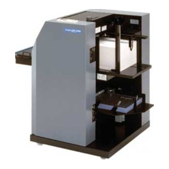
- Page 1 Duplo DSF-2000 Sheet Feeder Instruction Manual Provided By http://www.MyBinding.com http://www.MyBindingBlog.com...
-
Page 2: Sheet Feeder
SHEET FEEDER DSF-2000 INSTRUCTION MANUAL... -
Page 3: Declaration Of Conformity
(1993) + A1 (1997) + A2 (1999), EN55014-2 (1997), EN61000-3-2 (1995) + A1/A2 (1998), EN61000-3-3 (1995) ÜBEREINSTIMMUNGSERKLÄRUNG Die DUPLO CORPORATION mit Sitz in 7-6, Izumi honcho 1-chome, Komae-shi, Tokyo 201-8666, Japan, versichert, daß das folgende produkt, Bezeidhnung des Produkts : Bogen-Anleger : DSF-2000 220–240 V 50/60 Hz... -
Page 4: Table Of Contents
INTRODUCTION Thank you for purchasing this Duplo equipment. To ensure correct usage, please read this instruction manual thoroughly, especially the section Safety Precautions. After reading, please store this instruction manual in a safe place for future reference. TABLE OF CONTENTS Safety Precautions ........... -
Page 5: Safety Precautions
1. SAFETY PRECAUTIONS Always observe the cautions and warnings given below to prevent personal injury or property damage. The degree of danger and damage that could occur is indicated on two levels by the following marks. WARNING : Ignoring this mark could result in the possibility of serious injury or even death. - Page 6 Do not use flammable sprays inside or near the unit (e.g. when cleaning the unit). Such flammable gas may ignite and cause a fire or combustion. Make sure that the combined power consumption of the appliances to be connected does not exceed the capacity rating of the power outlets or plug receptacles.
-
Page 7: Warning And Caution Label Locations
SAFETY PRECAUTIONS (continued) Warning and Caution Label Locations... -
Page 8: Usage Precautions
2. USAGE PRECAUTIONS 2-1. Power Supply This equipment shall be installed near the socket-outlet where the plug on the power supply cord is easily accessible. Make sure the power supply used is always within the following range. 220 to 240 V AC, 50/60 Hz (120 V AC, 60 Hz) When you power other appliances from the same AC outlet, make sure that the combined power consumption does not exceed the power supply capacity. -
Page 9: Names And Operation Of Parts
3. NAMES AND OPERATION OF PARTS... - Page 10 3. NAMES AND OPERATION OF PARTS Name Operation Control panel For details, refer to “4. CONTROL PANEL”. Paper feeder A Paper feeder normally used. Paper feed tray A Stacks the paper to be bound. Auxiliary paper feed Prevents entangling of paper at the entrance of the paper feed tray A. plate A Remove when using paper less than 200 mm (7.87") wide.
- Page 11 3. NAMES AND OPERATION OF PARTS...
- Page 12 3. NAMES AND OPERATION OF PARTS Name Operation Paper feeder B Used to insert cover paper. Paper feed tray B Stacks cover paper. Stack guide B Holds the edge of cover paper stacked on the paper feed tray B, and maintains the position.
-
Page 13: Control Panel
4. CONTROL PANEL 4-1. Names and Operation of Control Panel q Display (LCD) e Stop button w Start button t Power ON indicator Clear Escape button button r Jog dial Function button Name Operation Display (LCD) Displays items, settings, and messages. Start button Press to operate the machine. -
Page 14: Control Panel Lcd And Selection Items On Lcd
4. CONTROL PANEL 4-2. Control Panel LCD and Selection Items on LCD The jog dial on the control panel is used to change and confirm items and values in this machine. Turning the jog dial switches the item displayed on the LCD in order, and pressing it confirms the mode or value changed to. - Page 15 4. CONTROL PANEL (2) LCD map The LCD map displays the hierarchy of the LCD in an easy to understand format. Turning the jog dial switches the display within the same hierarchy, and press to move to the hierarchy below (right side of the LCD map). If no hierarchy exists below, turning the jog dial selects an item or sets a value.
- Page 16 4. CONTROL PANEL B Sheet Set. Select B Sheet None Yes ∗ Endmark Set. Sensor1 Set. Sensor1 on/off Sensor1 on/off Off On ∗ Sensor1 Position Sensor1 Position 210 ∗ Sensor2 Set. Sensor2 on/off Sensor2 on/off Off On ∗ Sensor2 Position Sensor2 Position 210 ∗...
- Page 17 4. CONTROL PANEL Custom Size Custom 1 Size L=364 W=257 Length L= 364 Select Length L= 364 ∗ Width W= 257 Select Width W= 257 ∗ Custom 2 Size L=364 W=257 Length L= 364 Select Length L= 364 ∗ Width W= 257 Select Width W= 257 ∗...
- Page 18 4. CONTROL PANEL Tray Up/Down Tray Up/Down A Tray ∗ Tray Up/Down B Tray ∗ Other Setting Tone Tone on/off On Off ∗ LCD Setting Shift Speed Fast Select Shift Sp. Fast Normal Slow Very Slow ∗ Blink Speed Fast Select Blink Sp.
- Page 19 4. CONTROL PANEL D-feed Sensor A Tray Setting A Tray Check Check on/off Off On ∗ A Tray Thick Auto Select Thick Auto Heavy Thin ∗ A Tray Level 17 [%] Select Level 17 20 25 33 50 ∗ A Tray Position 120 [mm] Select Position 120 130 140 150 160 170 ∗...
- Page 20 4. CONTROL PANEL Check Mode Select Mode Sheet Set ∗ Blower Strength A.- 1 B.- 1 Blower Stre. A Select Stre. A 1 2 3 ∗ Blower Stre. B Select Stre. B 1 2 3 ∗ Feed Cl. Timing A.- 2 B.- 2 Clutch Timing A Select Timing A 1 2 3 4 5 6 ∗...
- Page 21 4. CONTROL PANEL (3) Error messages Displays error messages on the LCD when errors occur. “Sheet Feeder Initializing.” : Displayed at power ON and during initialization when the door is closed. “PAPER JAM” : Displayed when paper jam occurs. Displays the area of the jam at the bottom.
-
Page 22: Check This Before Use
5. CHECK THIS BEFORE USE 5-1. Turning ON the Power When connecting the DBM-120 Sheet by Sheet Turn ON the main power switch of the DBM-120 Sheet by Sheet and power switch of the DBM-120T, and press the ON side “I” of the main power switch of this unit. (Set the power switch of the DBM-120 Sheet by Sheet to OFF, push down the maintenance switch of the DBM-120T, and set the remote switch of this unit to the side (upper side).) -
Page 23: Up/Down Operations Of Paper Feed Tray
5. CHECK THIS BEFORE USE 5-2. Up/Down Operations of Paper Feed Tray Turn the jog dial at the initial screen and display “Tray Up/Down”, and press the jog dial to confirm the setting. Tray Up/Down A Tray To move the paper feed tray of the paper feeder A up and down, turn the jog dial and display “A Tray”... -
Page 24: Operations
6. OPERATIONS Stack paper and perform the various adjustments of the paper feed section. Refer to “15. STACKING PAPER ON THE PAPER FEEDER A AND ADJUSTING PAPER FEED” and “16. STACKING PAPER ON THE PAPER FEEDER B AND ADJUSTING PAPER FEED”. Perform the various settings according to the required operation on the control panel. - Page 25 6. OPERATIONS When connecting the DBM-400 Sheet by Sheet q Turn the jog dial at the initial screen to display the “Finisher Mode”, and press the jog dial to confirm the setting. Staple/Fold Mode Booklet w Turn the jog dial to display “Staple/Fold Mode”, and press the jog dial to confirm the setting. “Trimming Mode”...
- Page 26 6. OPERATIONS Enter the number of sets to be processed and the number of sheets in one set. NOTE : The cover page fed from the paper feeder B is not included in the number of sheets of the set. q Turn the jog dial at the initial screen to display “Number Of Job”, and press the jog dial to confirm the setting.
- Page 27 6. OPERATIONS Perform test feeding. This memorizes the features of the paper set in the machine. As this step is required for double-feed detection, automatic size detection, and end mark detection, be sure to perform this step. q Continue pressing the start button for more than two seconds, and release. (Pressing the start button generates one short beep and another beep two seconds later.
-
Page 28: Paper Feeder B (Cover Feeder)
7. PAPER FEEDER B (COVER FEEDER) The paper feeder B feeds cover paper. Use only when inserting cover paper. After the number of sheets set has been fed from paper feeder A, only one sheet will be fed from paper feeder B as the cover paper. 7-1. -
Page 29: End Mark Detection Function
8. END MARK DETECTION FUNCTION This machine comes with an end mark detection function at the paper feeder A. This function detects collation and paper feed errors, and prevents binding errors. There are two types of end mark detection functions: “Number/set check function” and “Random binding function”. -
Page 30: Setting The End Mark Detection Function
8. END MARK DETECTION FUNCTION 8-2. Setting the End Mark Detection Function Select whether to use or not use the end mark detection function, and set the position and processing method of the end mark if using the function. To use the end mark detection function, turn the jog dial at the initial screen to display “Endmark Set.”, and press the jog dial to confirm the setting. - Page 31 8. END MARK DETECTION FUNCTION Set the end mark position in respect to the paper feed direction. q With the “Sensor1 on/off” or “Sensor2 on/off” displayed (step 1), turn the jog dial, display “Sensor1 Position” to set the end mark position on the top face or “Sensor2 Position” to set the end mark position on the bottom face, and press the jog dial to confirm the setting.
-
Page 32: Printing The End Mark
8. END MARK DETECTION FUNCTION 8-3. Printing the End Mark Set only one end mark for solid printing (black) using a laser printer. For marks positioned along the vertical (paper feed) direction, the center is the standard position. But the setting can be changed by entering the desired position using numbers. (Refer to “8-2. -
Page 33: Reversal Mechanism
9. REVERSAL MECHANISM When the reversal mechanism is used, the paper fed using the paper feeder A can be reversed and sent to the downstream processing unit. 9-1. Selecting the Reversal Mechanism When using the reversal mechanism, turn the jog dial at the initial screen to display “Inverter Mode”... -
Page 34: Automatic Size Detection Function
10. AUTOMATIC SIZE DETECTION FUNCTION This machine is equipped with a function which automatically detects the paper size during test feeding without the need to input the paper size when saddle-stapling or center-folding specific standard size paper with the DBM-120 Sheet by Sheet. This function will not work if “Finisher Mode”... -
Page 35: Setting The Paper Size
11. SETTING THE PAPER SIZE To set the paper size, turn the jog dial at the initial screen to display “Paper Size”, and press the jog dial to confirm the setting. (The paper size need not be set for saddle-stapling and center-folding if the automatic size detection function has been set by connecting the DBM-120 Sheet by Sheet. - Page 36 11. SETTING THE PAPER SIZE Press the (Escape) button to return to the initial screen. The paper size selected will be displayed at the top left of the initial screen. 5555/7777(1O) NOTE : Some paper sizes cannot be set according to the “Finisher Mode” set. Refer to the following table. When connecting the DBM-120 Sheet by Sheet Finisher Mode Settable Paper Size...
-
Page 37: Custom Sizes
12. CUSTOM SIZES This machine is able to set three paper sizes (custom size) within the specification other than standard paper sizes. 12-1. Entering the Custom Size To enter the custom size, turn the jog dial at the initial screen to display “Custom Size”, and press the jog dial to confirm the setting. -
Page 38: Other Settings
13. OTHER SETTINGS Various settings are available according to purpose of use. After setting, press the (Escape) button until the initial screen is displayed. 13-1. Setting the Buzzer On/Off The buzzer which sounds when the jog dial or a button on the control panel is pressed or when an error occurs can be turned off. -
Page 39: Setting The Millimeters/Inches Display
13. OTHER SETTINGS 13-3. Setting the Millimeters/Inches Display The custom size entered can be displayed in millimeters or inches. Turn the jog dial at the initial screen to display “Other Setting”, and press the jog dial to confirm the setting. Turn the jog dial to display “mm/In Setting”, and press the jog dial to confirm the setting. -
Page 40: Changing The Set Speed/Paper Feed
13. OTHER SETTINGS 13-4. Changing the Set Speed/Paper Feed Speed (Changing the Processing Speed/Paper Feed Interval) This machine is able to change the time from one paper feed by the paper feeder A to the next paper feed (paper feed speed), and the time from the paper feed of the last paper in the set to the paper feed of the next set (set speed). -
Page 41: Setting The Double-Feed Detection Sensor
13. OTHER SETTINGS 13-5. Setting the Double-feed Detection Sensor The double-feed detection sensor compares the characteristics data of the paper test-fed and paper being processed, and determines that double-feeding has occurred when the difference in characteristics is large. The sensor also detects paper jams. The settings of the double-feed detection sensor of the paper feeder need to be changed according to the paper and purpose. - Page 42 13. OTHER SETTINGS (b) Setting the thickness of the paper Turn the jog dial to display “A Tray Thick”, and press the jog dial to confirm the setting. Turn the jog dial and display “Auto”, “Heavy”, or “Thin” at the left edge according to the paper used, and press the jog dial to confirm the setting.
- Page 43 13. OTHER SETTINGS (d) Setting the position for starting the double-feed detection Turn the jog dial to display “A Tray Position”, and press the jog dial to confirm the setting. Turn the jog dial and display the desired detection start position at the left edge, and press the jog dial to confirm the setting.
- Page 44 13. OTHER SETTINGS (2) Setting the double-feed detection sensor of the paper feeder B Select to use the double-feed detection function of the paper feeder B, and set the paper thickness, double- feed detection sensitivity, and position to start double-feed detection. Turn the jog dial to display “B Tray Setting”, and press the jog dial to confirm the setting.
- Page 45 13. OTHER SETTINGS (3) Setting the double-feed detection method There are two methods of double-feed detection: “Set” and “Sheet”. Turn the jog dial to display “Check Mode” at the top, and press the jog dial to confirm the setting. To set “Set”, turn the jog dial and display “Set” at the left edge, or to set “Sheet”, turn the jog dial and display “Sheet”...
-
Page 46: Selecting The Separator Air Strength
13. OTHER SETTINGS 13-6. Selecting the Separator Air Strength The separator air strength can be selected from three steps. If paper feed errors occur frequently at standard value “1”, change the setting and set the most appropriate value. If the paper is large and thick, set the air strength to high. -
Page 47: Setting The Driving Time Of Suction Belt
13. OTHER SETTINGS 13-7. Setting the Driving Time of Suction Belt The driving time of the suction belt (paper feed clutch connecting time) can be set. If paper feed errors occur frequently at standard value “2”, change the setting. When feeding long paper such as A3 paper, set a long suction belt driving time. -
Page 48: Setting Of No. Of Jogged Sheets
13. OTHER SETTINGS 13-9. Setting of No. of Jogged Sheets The timing for side jogging by the downstream processing unit (side jogging should be performed after how many sheets it has received from this machine) can be changed within the range of 1 to 5 sheets. -
Page 49: Page Order And Direction Of Paper On The Paper Feed Tray
14. PAGE ORDER AND DIRECTION OF PAPER ON THE PAPER FEED TRAY 14-1. Paper Stacked on Paper Feed Tray A (1) When saddle-stapling/folding or center-folding paper in the downstream processing unit Stack paper which has been collated in order on the paper feed tray A. Stack the paper in the order and direction shown in the figure. - Page 50 14. PAGE ORDER AND DIRECTION OF PAPER ON THE PAPER FEED TRAY (3) When saddle-stapling/folding or center-folding in the downstream processing unit using a reversal mechanism Order and direction of paper stacked on paper feed tray A Proceeding direction in downstream processing unit Paper feed direction (4) When side-stapling or corner-stapling in the downstream processing unit using a reversal...
-
Page 51: Paper Stacked On Paper Feed Tray B
14. PAGE ORDER AND DIRECTION OF PAPER ON THE PAPER FEED TRAY 14-2. Paper Stacked on Paper Feed Tray B (1) When saddle-stapling/folding or center-folding in the downstream processing unit Direction of cover paper stacked on paper feed tray B Proceeding direction in downstream processing unit Paper feed direction... -
Page 52: Stacking Paper On The Paper Feeder A And Adjusting Paper Feed
15. STACKING PAPER ON THE PAPER FEEDER A AND ADJUSTING PAPER FEED Move the auxiliary paper feed plate A to the appropriate position. Push and slide the center part of the auxiliary paper feed plate A to the left and right. Paper feed tray A Auxiliary paper feed plate A Set 0 to 10 mm (0 to 0.39") - Page 53 15. STACKING PAPER ON THE PAPER FEEDER A AND ADJUSTING PAPER FEED Set the rear guide A at the rear of the paper stacked. If the stacked paper is lower than the rear guide such as when only a small amount of paper is stacked, raise the paper feed tray A.
-
Page 54: Stacking Paper On The Paper Feeder B And Adjusting Paper Feed
16. STACKING PAPER ON THE PAPER FEEDER B AND ADJUSTING PAPER FEED Stack cover paper on the paper feed tray B. Arrange the tip and side of the cover paper properly, and stack it gently pressing against two guides so that there is no gap between the tip and right side (level sensor side) of the paper and each guide. -
Page 55: Auxiliary Stack Guide A
17. AUXILIARY STACK GUIDE A Use the auxiliary stack guide A if paper is fed crookedly. Place it on the paper feed tray A so that it presses the sponge at the position where the left side of the paper stacked or the rear end of the paper becomes crooked. Auxiliary stack guide A Paper feed tray A... -
Page 56: When Error Occurs
18. WHEN ERROR OCCURS 18-1. Correcting Paper Jamming When paper jamming occurs, open the upper door, lower door, and bridge door and remove the paper completely before resuming operation. If all of the doors are not opened and closed, the paper-jam error message will not go off even if the jammed paper has been removed and operations cannot be resumed. -
Page 57: When The Error Message "Paper Jam" Is Displayed At The Lcd
18. WHEN ERROR OCCURS 18-2. When the Error Message “PAPER JAM” is Displayed at the LCD When paper jamming occurs, “PAPER JAM” will be displayed in the first line of the LCD of the control panel, and the area of the jam will be displayed in the second line. “Feed”... -
Page 58: When The Machine Stops Due To Errors
18. WHEN ERROR OCCURS 18-3. When the Machine Stops Due to Errors If this unit stops due to error while operating, restart this unit using the following methods. (1) To resume operations from where the machine stopped, perform the following operations according to the cause of the error. -
Page 59: When The Error Message "Finisher Error" Is Displayed At The Lcd
18. WHEN ERROR OCCURS 18-4. When the Error Message “Finisher Error” is Displayed at the LCD When error occurs in the downstream processing unit, “Finisher Error” will be displayed in the first line of the LCD of the control panel of this unit, and the error details will be displayed in the second line. -
Page 60: When The Error Message "Malfunction" Is Displayed
Please let the service personnel have the following information: Your name (or the name of the company and person in charge), address, and telephone number The model name: DSF-2000 (Sheet feeder) Product number The message displayed in the second line of the display... -
Page 61: Cleaning
20. CLEANING Once a day, clean the conveyance roller and suction belt for conveying paper. Problems may occur if the conveyance roller and suction belt are dirty. Clean by wiping the dirty areas with a cloth moistened with water or alcohol. To perform operations after cleaning, do so after making sure the cleaned areas have dried completely. -
Page 62: Troubleshooting
21. TROUBLESHOOTING Symptom Cause Remedy Double-feeding occurs Improper adjustment of paper Adjust the level sensor, separator air, frequently. feeder. and separator of each paper feeder. (Refer to “15. STACKING PAPER ON T H E P A P E R F E E D E R A A N D ADJUSTING PAPER FEED”... -
Page 63: Specifications
Additional function Reversal function (paper feeder A only) DSF-2000: W × D × H = 1100 × 750 × 1015 mm (43.31" × 29.53" × 39.96") Dimensions DSF-2000 + DBM-120 Sheet by Sheet + DBM-120T + Stacker: W ×... - Page 64 99T-90182-01080000M-0 This manual is printed on recycled paper to help protect the environment.
Need help?
Do you have a question about the DSF-2000 and is the answer not in the manual?
Questions and answers