
Related Manuals for Watchguard ALC-CAM2


Summary of Contents for Watchguard ALC-CAM2
- Page 1 ALC-PACK3 WiFi Alarm System with HD WiFi Camera User Manual Your Watchguard Wireless Security professional: www.activeonline.com.au 1300 816 742...
- Page 2 Foreword Congratulations on your purchase of the ALC-PACK3 Alarm system. Before you commence installation, we recommend that you unpack the product, familiarise yourself with the component parts, and carefully read through this instruction guide. There are some parts of the installation must be completed in the order shown to ensure successful installation.
-
Page 3: Table Of Contents
Contents Packing List ............................1 Hub ..............................2~3 Remote Control .............................4 Door/Window Contact ........................5 Pairing New Accessories to the Hub .....................6 Getting Started ..........................6-7 App Control and Settings ......................8-14 Interference Detection ........................14 Restoring to Factory Settings ......................14 Installation ............................. 15-16 Replacing Accessory Batteries ......................17 FAQ .............................. -
Page 4: Packing List
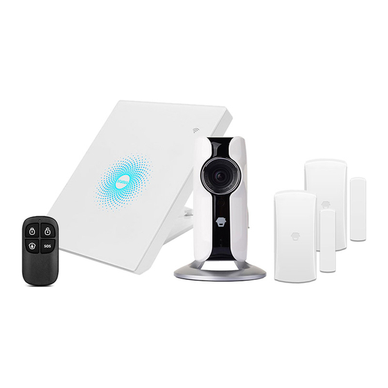
Packing List 1x ALC-PACK3 Hub / Control Panel status 1x ALC-CAM2 720p HD WiFi Camera 2x ALC-RSW1 Door/ Window Contact 1x ALC-RC1 Remote Control 2x Power Adapter 1x Camera Reset Pin... -
Page 5: Hub
All Sensors are wirelessly linked to the Hub. In the event of alarm activation, for example, when a Sensor is triggered, a push notification will automatically be sent to all registered users The system can be controlled and monitored both on-site using the Remote Control supplied and remotely from anywhere in the world, with the FREE iOS and Android Apps. - Page 6 LED Indication Steady On Connected with Router WiFi Indicator Searching for a network or disconnected One flash per second (Blue) from Router The Power Adapter is not plugged in Steady On Stable WiFi connection System is Armed Blue System is in Home Mode (Part Arm) Status Green System is Disarmed...
-
Page 7: Remote Control
Remote Control The Remote Control can be used to arm, part arm or disarm the system, and trigger an emergency alarm (SOS). Status Indicator Disarm Home Arm (Part Arm) SOS Button Button System Status All Sensors will be Armed. This mode is for use when the property is unoccupied. The System will be Disarmed, no Sensors will be triggered. -
Page 8: Door/Window Contact
Door/ Window Contact Door/ Window Contacts are set to ‘Normal Zone’ by default and are ideal for protecting entry/exit points such as front and back doors and windows. When the system is Armed, should a Door Contact be triggered (Magnet separated from the Transmitter), a push notification showing the named Sensor will automatically be sent to the registered users and the Hub Internal Siren will sound immediately. -
Page 9: Pairing New Accessories To The Hub
Pairing New Accessories to the Hub There are two ways of pairing Accessories to the Hub – manually and via App. Manual Pairing To pair Accessories manually please follow the instructions below: Remote Control and Sensors: 1. Press the Learn button at the back of the Hub 2. - Page 10 Step Two: Sign Up / In Press the "Sign up" button on the page, and follow the instructions to create your account first. Once you have an account, select the "Sign in" button to enter the operation page. Step Three: Connect the Hub to Your Router Power on the Hub, then follow the configuration steps on App to set up your Hub with your home WiFi.
-
Page 11: App Control And Settings
APP Control and Settings History & Setting Account Management System Status Disarm Home Arm (Part Arm) Important Notice In order to control the system remotely (WiFi/App), the Hub must be ‘mains’ pow- ered via the Power Adapter. WiFi accessibility is disabled after 2 mins and the Hub beeps 30 times when the Hub Power Adapter is unplugged from the mains power supply and running on batteries. - Page 12 System Disarmed All the sensors stop detecting except any sensors that you may have set to Instant Alarm Zone (they will continuously monitor a particular area). For example, an extra Water Sensor which has been set to Instant Alarm Zone by default and installed near a washing machine would trigger alarm if water is detected, regardless of sys- tem status.
-
Page 13: Internal Siren
Zone Mode Activated Zone Sensors set to Activated Zone are armed when the system is in Arm (Full Arm) or Home Arm (Part Arm) Mode. We recommend setting Window/Door Sensors to this zone because they would always be installed to the perimeter of a house in practice, like doors or windows. - Page 14 Delay Settings Exit Delay Time Set a time delay for you to leave your property without triggering an alarm. Entry Delay Time (Available only for Alarm Delay Zone Sensor) Set a time delay for you to enter your property without triggering an alarm. Timed Arm/Disarm The system can be programmed to automatically Arm and Disarm the alarm at predefined times by following the steps below:...
- Page 15 Notifications 1. Alert Tone This setting enables you to select a ringtone for alarm notification as you like. 2. Email This setting enables you to add mailboxes to receive alarm notifications. Account Management Tap the [ ] icon on the top left of the main page, click the portrait to enter the account management.
- Page 16 Adding More Devices One account can achieve operating multiple devices in this App, if you have multiple ALC-PACK3 Hubs or cameras, it is easy for you to manage these devices within this App. Tap the [ ] icon, you can add the device you want. If you want to delete the accessory, just press and slide the accessory to the left and then delete it.
-
Page 17: Interference Detection
It is highly recommended that you set access limits to those who you may share your device(s) with. In choosing not to do so, you grant your family and/or friends continual access to the device(s) you have shared. Interference Detection The ALC-PACK3 Hub has a feature of interference-Detection. -
Page 18: Installation
Installation Wall Mounting The Hub can be wall mounted using the Wall Bracket provided. Using the screws supplied, mount the Wall Bracket onto the wall (ensuring that the arrow on the bracket is pointing upwards), then match-up the Wall Bracket hooks to the holes ①... - Page 19 Door/ Window Contact : Step 1: To power up the Contact, remove the Battery Tab Step 2: Attach the Adhesive Pads to the back of the Transmitter and Magnet Step 3: Place the Contact on the door/ window frame and the magnet on the door/ window ensuring that the distance between them is not greater than 1cm when the door/ window is shut.
-
Page 20: Replacing Accessory Batteries
Replacing Accessory Batteries Remote Control Remove the screw Open the casing Door/Window Contact Open the casing Failed to connect to the WiFi Check whether the WiFi Indicator on the Hub has stopped flashing If the WiFi Indicator stops flashing and the Hub cannot be controlled from the App, please make sure that your local WiFi network is available and working properly. - Page 21 The WiFi indicator and the status indicator are on, but I can’t control the alarm by Check that your smartphone is connected to a WiFi network. Wait a few minutes to see if the WiFi indicator and the status indicator start flashing.
-
Page 22: Specifications
Specifications Power Supply DC 12V 500 mA Battery 3.7V 700mAh Polymer Battery Battery Life Recharge Cycle 300 times WiFi IEEE 802.11b/g/n Standby Current <50mA Alarm Current <90 mA Internal Siren 90 dB Optional Accessories 10 Remote Controls, 50 Sensors Radio Frequency 315MHz or 433.92MHz Housing Material ABS Plastic... - Page 23 Door/ Window Contact Power Supply DC 1.5V (1.5V AA LR6 battery x 1pc) Static Current <35 uA Alarm Current <40 mA Transmitting Distance <80 m (open area/no interference) Radio Frequency 315MHz or 433.92 MHz Housing Material ABS Plastic Temperature 0°C~+55°C Operating Condition Relative Humidity <80% (non-condensing) Transmitter Dimensions...
- Page 24 © 2017 Watchguard Systems . All Rights Reserved.
Need help?
Do you have a question about the ALC-CAM2 and is the answer not in the manual?
Questions and answers