Advertisement
Quick Links
Advertisement

Related Manuals for DUDOFF GI-Z0102


Summary of Contents for DUDOFF GI-Z0102
- Page 1 INSTALLATION AND USER INSTRUCTIONS BUILT-IN MIXED HOB, INDUCTION DOMINO HOB...
- Page 2 WARNING: The appliance and its accessible parts become hot during use. Care should be taken to avoid touching heating elements. Children less than 8 years of age shall be kept away unless continuously supervised. This appliance can be used by children aged from 8 years and above and persons with reduced physical, sensory or mental capabilities or lack of experience and knowledge if they have been given supervision or instruction concerning use of the appliance in a safe...
-
Page 3: Cooking Area
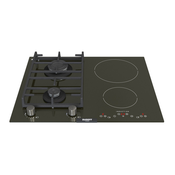
DESCRIPTION COOKING AREA TYPE: PCZ VTCI The appliance has 2 cooking areas with different sizes and different power levels. The induction elements are of the magnetic induction type, which come on after selecting the heating element, and the heat can be regulated using the controls on the front panel, from a minimum of 1 to a maximum of 9 (depending on the models). -
Page 4: Description Of Front Panel Controls
DESCRIPTION DESCRIPTION OF FRONT PANEL CONTROLS 2 INDUCTION ELEMENT 1 - Induction element 1 – button 2 - Induction element 1 + button 3 - ON/OFF button 4 - TIMER programming – button 5 - Clock levels display 6 - TIMER programming + button 7 - Safety lock button 8 - Induction element 2 –... -
Page 5: Instructions For The User
DESCRIPTION INITIAL LIGHT CONDITIONS When power is initially applied to the Cooktop, the touch control conducts a calibration process for the touch keys, which requires a low level of ambient light in the area of the touch keys. If during this calibration process excessive ambient lighting is detected the User Interface displays “FL” (Infrared Ambient Light Error) and the control calibration process is suspended. - Page 6 DESCRIPTION TIMER There is a timer for setting cooking times from 1 to 99 minutes (symbol After activating the cooking area required, selecting it on the display, activate the timer by pressing the symbol above the symbol. Then return to the heating element to be programmed by pressing its symbol.
- Page 7 WARNINGS: - If the power level does not change during a see figure 1 for correct use, and remember: set period of time, the corresponding heating - only connect the power supply after placing element switches off automatically. The the pan on the cooking area. maximum time that a heating element can - Use pans with a thick, flat bottom.
- Page 8 DESCRIPTION TYPE: PCZVB The appliance has 2/4 cooking areas with different sizes and different power levels. The heating elements are of the magnetic induction type, which come on after selecting the heating element, and the heat can be regulated using the controls on the front panel, from a minimum of 1 to a maximum of 9 (depending on the models).
- Page 9 DESCRIPTION DESCRIPTION OF FRONT PANEL CONTROLS DESCRIPTION OF FRONT PANEL CONTROLS 60 cm. 1 - Induction element 6 – button 7 - Safety lock button 2 - Induction element 6 + button 8 - Induction element 7 – button 3 - ON/OFF button 9 - Induction element 7 + button 10 - Display cooking levels (0 - 9) 4 - TIMER programming –...
- Page 10 1) TRADITIONAL BURNERS Burners Power W Ø Pan cm A diagram is screen-printed above each knob on the front panel. This diagram indicates to which Double crown 5000 24 ÷ 26 burner the knob in question corresponds. After Triple crown 4000 24 ÷...
- Page 11 WARNINGS AND ADVICE FOR THE USER: - use of a gas cooking appliance produces heat and moisture in the room in which it is installed. The room must therefore be well ventilated by keeping the natural air vents clear (fig. 3) and by activating the mechanical aeration device (suction hood or electric fan fig.
- Page 12 WARNING FOR USE: ► The appliance is built to perform the following function: cooking and heating food. Every other use must be considered improper. ► Never use this appliance to heat the environment. ► Do not attempt to change the technical characteristics of the product because it can be dangerous.
- Page 13 ARRANGEMENT OF THE HEATING ELEMENTS Model: 60 cm. FRONT BACK Every time the hob is reconnected to the electricity supply, the control panel lock is active and the relative led in on. After removing the control panel lock (by pressing the symbol for 1 second), switch on the hob by pressing the key for a few seconds.
- Page 14 KEY LOCK FUNCTION ): this function prevents the hob from being accidentally switched on (child safety Lock Function ( lock). To activate it, the sensor must be pressed for about three seconds (the warning light comes on). It is not possible to make the heating areas work if is active.
- Page 15 TIMER There is a timer for setting cooking times from 1 to 99 minutes (symbol After activating the cooking area required, selecting it on the display, activate the timer by pressing the symbol above the symbol. Then return to the heating element to be programmed by pressing its symbol.
- Page 16 3) GUIDE TO COOKING The table below indicates the power values that can be set and the type of food to prepare is shown next to each one. The values can change according to the amount of food and consumer preference. TABLE Power and dimensions of the cooking area...
- Page 17 WARNINGS: - If the power level does not change during a see figure 7 for correct use, and remember: set period of time, the corresponding heating - only connect the power supply after placing element switches off automatically. The the pan on the cooking area. maximum time that a heating element can - Use pans with a thick, flat bottom.
- Page 18 CLEANING IMPORTANT: always disconnect the appliance from the gas WARNINGS: and electricity mains before carrying out any comply with the following instructions, before cleaning operation. remounting the parts: ●check that burner head slots “T” (fig. 8/A) 4) CERAMIC WORKTOP have not become clogged by foreign bodies. It is very important to clean the hob every time you ●Check that enamelled burner cap “A”, “B”...
-
Page 19: Induction Cooking
INSTALLATION ADDITIONAL WARNINGS - After a period of time may appear metal reflex and scratches (fig. 9/A) due to the wrong Depending on the degree of dirt, we recommend: cleaning and the wrong use of the pots. The - for light stains, a damp sponge is sufficient. scratches are difficultly removable, but they do - Tough, encrusted dirt is easily eliminated using a not compromise the good working of the hob. -
Page 20: Technical Information
INSTALLATION TECHNICAL INFORMATION The packing elements (cardboard, bags, FOR FITTERS polystyrene, nails...) must not be left within the installation, transformation reach of children as they are potential sources maintenance operations listed in this section of danger. must be carried out exclusively by qualified It is necessary to make a hole in the kitchen unit to personnel. - Page 21 INSTALLATION 6) FITTING THE HOB - For the gas: fix the hob with the proper hooks “S” and fit the prominent part into the porthole The hob is equipped with a special seal to “H” on the bottom; turn the screw “F” until the avoid any infiltration of liquid into the unit.
- Page 22 INSTALLATION Positioning hooks TYPE: PCZ VTCI 30 cm. TYPE: PCZVB 60 cm. 90 cm. induction induction hook A (gas) hook B (induction) FIG. 15 FIG. 15/A...
- Page 23 INSTALLATION IMPORTANT INSTALLATION 9) GAS CONNECTION SPECIFICATIONS Before connecting the appliance, check that The installer should note that the appliance the values on the data label affixed to the that side walls should be no higher than the underside of the cooktop correspond to those cooktop itself.
- Page 24 INSTALLATION 10) ELECTRICAL CONNECTION When the appliance is connected straight to the electricity main: - install an omnipolar circuit-breaker between the IMPORTANT: the appliance must be appliance and the electricity main. This circuit- installed following the manufacturer's breaker should be sized according to the load instructions.
- Page 25 INSTALLATION 30 cm. - 60 cm. induction FIG. 16 TYPE AND SECTION OF THE POWER CABLES (see figure above) Monophase Type of cable power supply 220 - 240 V Hob gas H05 RR-F 3 x 0.75 mm H07 RN-F 3 x 1.5 mm Hob induction H05 VV-F ATTENTION!!!
- Page 26 INSTALLATION 90 cm. FIG. 16/B FIG. 16/A FIG. 16/C FIG. 16/D TYPE AND SECTION OF THE POWER CABLES (see figure above) Monophase Three-phase Two-phase power supply power supply power supply Type of cable 220 - 240 V 380 - 415 V 3N 380 - 415 V 2N H05 RR-F 3 x 0.75 mm...
- Page 27 SETTING THE POWER 11) SETTING THE POWER unlocked and all the heating elements must be The maximum power limit of the hob is 7200 W. switched off; This power limit can be reduced to 2800 W, 3500 ● press the front left heating element 7 and the W or 6000 W.
- Page 28 SETTING THE POWER The sequence for registering the new Power Limit for the hob is: ● press the front left heating element 7 and the front right heating element 6 selection keys together (see fig. 20); FIG. 20 ● after performing this operation, the new Power Limit of the hob is registered and the system resets itself. To end without registering any change ●...
- Page 29 ADJUSTMENTS Always disconnect the appliance from the The flame should not be too low: the lowest small electricity main before making flame should be continuous and steady. Re- adjustments. assemble the several components. All seals must be replaced by the technician at It is understood that only burners operating the end of any adjustments or regulations.
- Page 30 CONVERSIONS 13) REPLACING THE INJECTORS The envelope with the injectors and the labels can be included in the kit, or at disposal to the The burners can be adapted to different types of gas by authorized Customer Care Department. installing injectors suited to the type of gas required. To For the sake of convenience, the nominal rate chart also do this, first remove the burner tops using a wrench “B”.
- Page 31 SERVICING POWER RATINGS OF THE ELECTRICAL COMPONENTS POWER DENOMINATIONS Ø (cm) with booster Element heating induction 14,5 1200 1600 Element heating induction 21,0 1500 2000 WARNING: MAINTENANCE MUST ONLY BE PERFORMED BY AUTHORISED PERSONS. IF THE POWER CABLE IS DAMAGED, SHOULD BE REPLACED BY THE MANUFACTURER OR ITS AFTER SALES SERVICE.
-
Page 32: Displaying Special Statuses
DISPLAY OF ERRORS DISPLAYING SPECIAL STATUSES The corresponding heater display alternates between two characters depending on the status. Heater Heater Event Start Heater display display Action (Visualization conditions conditions status fore back Priority Order) (1 sec.) (1 sec.) Power increment Asked Cooktop Power not allowed... - Page 33 DISPLAY OF ERRORS Heater errors Heater errors are the errors which generate the switch off of one or more heaters. When a heater error is detected, the involved heaters are switched off, a beep sounds (only if one or more heaters are active) and the displays corresponding to these heaters show a “F” letter and the error code alternately.
- Page 34 DISPLAY OF ERRORS Errors/Alarms Appliance errors Appliance errors are the errors which generate the deactivation of the whole cooktop. When an appliance error is detected, all heaters are switched off, a beep sounds (only if one or more heaters are active) and all displays show a “F” letter and the error code alternately. While in error status all the heater keys are not operative.
- Page 35 TECHNICAL DATA ON THE DATA LABEL 2 BURNERS (60) 1 BURNER (60) (Aux + Rapid) (double crown 5.0 kW) CATEGORY = II CATEGORY = II 2 H3+ 2H3+ G 30 - BUTANE = 28 - 30 mbar G 30 - BUTANE = 28 - 30 mbar G 31 - PROPANE = 37 mbar G 31 - PROPANE = 37 mbar G 20 - NATURAL = 20 mbar...
-
Page 36: Technical Assistance And Spare Parts
TECHNICAL DATA FOR THE APPLIANCE GAS REGULATION TECHNICAL ASSISTANCE AND SPARE PARTS Before leaving the factory, this appliance will have been tested and regulated by expert and specialized personnel in order to guarantee the best performances. Any repairs or adjustments which may be subsequently required may only be carried out by qualified personnel with the utmost care and attention.
Need help?
Do you have a question about the GI-Z0102 and is the answer not in the manual?
Questions and answers