Advertisement
Quick Links
Advertisement

Related Manuals for DUDOFF G03-Z3


Summary of Contents for DUDOFF G03-Z3
- Page 1 INSTALLATION AND USER INSTRUCTIONS BUILT-IN GAS HOB (TOUCH CONTROL)
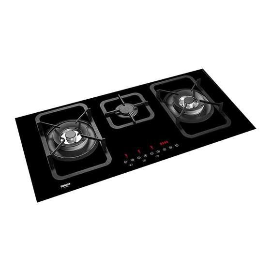
- Page 2 DESCRIPTION OF HOBS TYPE: MCGOG 78 cm. 78 cm. 86 cm. 78 cm. 86 cm. 86 cm. 2 Triple Ring 3750 - 3800 W 3 DUAL burner 4200 W 4 Auxiliary burner 1000 W 5 Grid lateral 6 Grid central 7 Touch control Hob equipped with electronic burner management system, with touch panel burner control.
- Page 3 DESCRIPTION OF THE FRONT PANEL CONTROLS 3F of 78/86 cm. 1 - Burner 2 – button (left) 7 - Clock button 2 - Burner 2 + button (left) 8 - Safety lock button 3 - Burner 4 – button 9 - ON/OFF button 4 - Burner 4 + button 10 - Capacity levels display (0 - 9) 5 - Burner 2 –...
- Page 4 2F DA 78/86 cm. 1 - Burner 2 – button (left) 8 - Safety lock button 2 - Burner 2 + button (left) 9 - ON/OFF button 3 - Burner 2 – button (right) 10 - Capacity levels display (0 - 9) 4 - Burner 2 + button (right) 11 - Display clock 7 - Clock button...
- Page 5 1) BURNERS On the surface of the hob, there is a serigraphic figure above each knob, indicating the burner to which the knob refers. After turning on the gas at the main or opening the valve on the gas bottle, light the burners as indicated below.
- Page 6 Switching off a burner To switch off a burner it is necessary to press the + and - button simultaneously for a moment. The corresponding Led will display the letter “H” (hot) for a few minutes to indicate that the burner is hot. The Dual burner, instead, can be switched off in two ways depending on whether it is lit partially (internal ring) or completely (internal and external ring).
- Page 7 Regulating the clock Following interruptions to the power supply, it is necessary to set the time displayed by the clock inside the hob. To regulate the clock, press the buttons 7 and 8 together for at least 3 seconds. The flashing digit to the left of the dot indicates the hours, while those to the right indicate the minutes. It is possible to increase or decrease the hours using buttons 2 or 1 and by keeping buttons 2 or 1 pressed the change in the number of hours takes place continuously.
- Page 8 bottom on the burner, as these may tip or spill Burners Power W Ø pan cm their contents, causing accidents. - The pans must not extend beyond the edge of DUAL total 4200 22 ÷ 27 the hob. 8 ÷ 16 DUAL central - The machine must not be used by people (including children) with impaired mental or...
- Page 9 WARNINGS AND ADVICE FOR THE USER: - use of a gas cooking appliance produces heat and moisture in the room in which it is installed. The room must therefore be well ventilated by keeping the natural air vents clear (fig. 3) and by activating the mechanical aeration device (suction hood or electric fan fig.
- Page 10 CLEANING CAUTION: Do not allow vinegar, coffee, milk, salted water, before cleaning the appliance, disconnect it lemon or tomato juice from remaining in contact from the gas and electricity supplies. with the enamelled surfaces for long periods of time. 2) WORKTOP WARNINGS: It is very important to clean the hob every time you comply with the following instructions, before...
-
Page 11: Technical Information
INSTALLATION TECHNICAL INFORMATION ●Before entry into operation, check the wiring carefully: incorrect wiring may damage the device FOR FITTERS and jeopardise the safety of the system. Installation regulation, ●Connect and disconnect the hob only after cutting transformation and maintenance operations off the electricity supply. - Page 12 INSTALLATION 3A) CYLINDER HOLDER COMPARTMENT IMPORTANT: The dimensions of the cylinder compartment have to a perfect installation, adjustment permit the easy loading and unloading of the cylinder. transformation of the cook top to use other For an efficient aeration is necessary to make some gases requires a QUALIFIED INSTALLER: a small openings in the furniture, as per fig.
- Page 13 INSTALLATION unit must be able to resist temperatures of at 4) FITTING THE HOB least 150 °C to prevent the coating from The hob is equipped with a special seal to avoid becoming unstuck. any infiltration of liquid into the unit. To apply this The appliance must be installed in compliance seal correctly, please follow the instructions given with the indications of the standards in force.
- Page 14 INSTALLATION When the gas is delivered directly from a 7) GAS CONNECTION bottle, the appliance, fed with a pressure regulator Before connecting the appliance, ensure that compliant with the standards in force must be the data on the label applied to the lower part connected: is compatible with that of the gas distribution ●with copper piping compliant with the standards...
- Page 15 INSTALLATION We strongly recommend that you connect the 8) ELECTRICAL CONNECTION appropriate green-yellow earth wire to an efficient earth system. IMPORTANT! Before performing any service on the electrical The appliance must be installed following part of the appliance, it must absolutely be the manufacturer's instructions.
- Page 16 REGULATION AND TRANSFORMATION OPERATIONS The regulation operations listed below are reserved to qualified fitters only. After carrying out any regulation or pre-regulation operations, any seals must be replaced by the technician. The regulation of primary air to our burners is not necessary. 9) PROCEDURE FOR REGULATING THE MINIMUM CAPACITY OF THE BURNERS The procedure for acquiring the minimum capacities allows the modification of the minimum capacity...
- Page 17 REGULATION AND TRANSFORMATION OPERATIONS previously applied. This label is contained in 10) REPLACING NOZZLES the spare nozzle bag. The burners can be adapted to suited different For the ease of the fitter, we have prepared a table types of gas by fitting the nozzles that correspond indicating the flow capacities, the heat capacities to the gas used.
- Page 18 REGULATION AND TRANSFORMATION OPERATIONS Display of the temperature inside the hob There is a temperature sensor inside the electronic card with which it is possible to show the temperature inside the hob directly on the timer display. The display is activated by pressing the 2 and 1 buttons with buttons 7 and 8 continuously for at least 3 seconds.
- Page 19 REGULATION AND TRANSFORMATION OPERATIONS MEASUREMENTS (electronic card)
- Page 20 MAINTENANCE Before carrying maintenance, • In the event of a “partial” short circuit or insufficient disconnect the appliance from the gas and insulation between the line and earth, the voltage electricity supplies. on the sensor electrode may be reduced so much that it causes the device to lock, due to the INDICATIONS FOR INSTALLATION impossibility to sense the flame signal.
- Page 21 MAINTENANCE POWER CABLE TYPES AND SECTIONS CABLE TYPE OF HOB TYPE OF POWER MONOPHASE Gas hob H05 RR-F Section 3 x 0.75 mm CAUTION!!! When replacing the power cable, the fitter must keep the earth conductor “B” longer than the phase conductor (fig.
-
Page 22: Technical Data
TECHNICAL DATA DESCRIPTION The electronic card enables the management of a gas hob with 2/3 burners. This device works in conjunction with the Brahma VPC01 valves, which allow the regulation of the capacity of each individual burner powered by methane gas or lpg. The device is also made up of a user interface with display in seven segments and a touch panel. - Page 23 TECHNICAL DATA PRINTED ON THE LABEL 3 BURNERS (86) 2 BURNERS (86) ( 2 Triple Ring + 1 AUXILIARY ) ( 1 DUAL + 1 Triple Ring ) G30 - BUTANE = 28 - 30 mbar G30 - BUTANE = 28 - 30 mbar G31 - PROPANE = 37 mbar G31 - PROPANE = 37 mbar G20 - NATURAL = 20 mbar...
- Page 24 TECHNICAL ASSISTANCE AND SPARES Before leaving the factory, this appliance was tested and regulated by specially qualified experts in order to guarantee the best operating results. The original spare parts can be found only in our Technical Assistance Centres and authorised shops. Every repair or regulation operation which should become subsequently necessary must be carried out with the utmost care and attention by qualified personnel.
Need help?
Do you have a question about the G03-Z3 and is the answer not in the manual?
Questions and answers