Phytec PhyBOARD-Mira i.MX6 Hardware Manual
Hide thumbs
Also See for PhyBOARD-Mira i.MX6:
- Quick start manual (2 pages) ,
- Quick start manual (2 pages)
Table of Contents

Related Manuals for Phytec PhyBOARD-Mira i.MX6


Summary of Contents for Phytec PhyBOARD-Mira i.MX6
- Page 1 ® phyBOARD -Mira i.MX 6 Hardware Manual Document No.: L-843e_0 SBC Prod. No.: PB-01501-xxx CB PCB No.: 1434.3, 1434.4 SOM PCB No.: 1429.3, 1429.4, 1429.5 Edition: Oktober 2017 A product of a PHYTEC Technology Holding company...
- Page 2 GmbH neither gives any guarantee nor accepts any liability whatsoever for consequential damages resulting from the use of this manual or its associated product. PHYTEC Messtechnik GmbH reserves the right to alter the information contained herein without prior notification and accepts no responsibility for any damages that might result.
- Page 3 3.2 System Level Hardware Information ..............36 3.2.1 Soldering Jumpers ................36 3.2.2 USB Connectivity ................37 3.2.2.1 Rerouting the USB Interfaces to other Connectors (J5, J6, J9 and J10)..................37 3.2.2.2 Configuring the OTG Operating Mode (R10) .......37 PHYTEC Messtechnik GmbH 2017 L-843e_0...
- Page 4 C Connectivity ................38 3.2.5 LVDS connector (X9)................. 39 3.2.6 Mini PCI Express Connector (X7)............42 3.2.7 Audio/Video connectors (X13 and X14) ..........44 3.2.8 Expansion Connector (X17)..............47 Revision History....................51 Index ........................53 PHYTEC Messtechnik GmbH 2017 L-843e_0...
- Page 5 Figure 17: Backlight and Display Control Connector X8 ............32 Figure 18: Touch Screen Connectors X21 ...............33 Figure 19: Boot Switch (S2)..................34 Figure 20: System Reset Button S1................34 Figure 21: Audio/Video Connectors (X13and X14)............44 Figure 22: Expansion Connector (X17)................47 PHYTEC Messtechnik GmbH 2017 L-843e_0...
- Page 6 Mini PCI Express Connector X7 ..............42 Table 25: Phytec A/V connector X14................45 Table 26: Phytec A/V connector X13................46 Table 27: A/V Jumper Configuration J1............... 47 Table 28: Phytec Expansion Connector X17 ..............48 PHYTEC Messtechnik GmbH 2017 L-843e_0...
- Page 7 (command, program execution, etc.) Abbreviations and Acronyms Many acronyms and abbreviations are used throughout this manual. Use the table below to navigate unfamiliar terms used in this document. PHYTEC Messtechnik GmbH 2017 L-843e_0...
- Page 8 Solderless jumper, these types of jumpers can be removed and placed by hand with no special tools Not Connected Not Mounted Not Specified Printed circuit board Phytec Display Interface, defined to connect Phytec display adapter boards, or custom adapters Phytec Expansion Board PMIC Power management IC Power over Ethernet...
- Page 9 Preface At this icon you might leave the path of this Application Guide. This is a warning. It helps you to avoid annoying problems. You can find information to solve problems. PHYTEC Messtechnik GmbH 2017 L-843e_0...
- Page 10 ® As a member of Phytec's new phyBOARD product family the phyBOARD-Mira i.MX 6 is one of a series of Phytec System on Modules (SBCs) that offer off-the-shelf solutions for a huge ® variety of industrial applications. The new phyBOARD...
- Page 11 SBC lies in its layout and test. Software Support Production-ready Board Support Packages (BSPs) and Design Services for our hardware will further reduce your development time and risk and allow you to focus on your product expertise. PHYTEC Messtechnik GmbH 2017 L-843e_0...
-
Page 12: Ordering Information
OEM modules, which can be embedded directly into the user’s peripheral hardware design. Take advantage of Phytec products to shorten time-to-market, reduce development costs, and avoid substantial design issues and risks. With this new innovative full system solution you will be able to bring your new ideas to market in the most timely and cost-efficient manner. - Page 13 Caution! Phytec products lacking protective enclosures are subject to damage by ESD and, hence, may only be unpacked, handled or operated in environments in which sufficient precautionary measures have been taken in respect to ESD-dangers. It is also necessary that only appropriately trained personnel (such as electricians, technicians and engineers) handle and/or operate these products.
- Page 14 Product Change Management and information in this manual on parts populated on the SOM / SBC When buying a Phytec SOM / SBC, you will, in addition to our HW and SW offerings, receive a free obsolescence maintenance service for the HW we provide.
-
Page 15: Introduction
(PCL-058), a connector-less, BGA style variant of the PCM-058/phyCORE-i.MX 6 SOM. The PCL-058 SOM is directly soldered down to the phyBOARD-Mira using Phytec's Direct Solder Connect technology. This solution offers an ultra-low cost Single Board Computer for the i.MX 6 processor, while maintaining most of the advantages of the SOM concept. - Page 16 One touch interface at 1x4 pin header 2.54 mm One LVDS camera interfaces compatible to Phytec phyCAM-S+ camera standard with I for camera control One PCI interface brought out to a Mini PCI Express connector, SIM-card signals are also available at the expansion connector ...
-
Page 17: Block Diagram
Introduction 1.1.2 Block Diagram Figure 1: Block Diagram of the phyBOARD-Mira i.MX 6 PHYTEC Messtechnik GmbH 2017 L-843e_0... -
Page 18: View Of The Phyboard-Mira I.mx 6
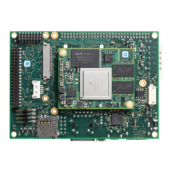
6 [PB-01501-xxx] 1.1.3 View of the phyBOARD-Mira i.MX 6 Figure 2: View of the phyBOARD-Mira i.MX 6 (top) PHYTEC Messtechnik GmbH 2017 L-843e_0... -
Page 19: Figure 3: View Of The Phyboard-Mira I.mx 6 (Bottom)
Introduction Figure 3: View of the phyBOARD-Mira i.MX 6 (bottom) PHYTEC Messtechnik GmbH 2017 L-843e_0... -
Page 20: Accessing The Phyboard-Mira Features
6 [PB-01501-xxx] Accessing the phyBOARD-Mira Features Phytec phyBOARD-Mira is fully equipped with all mechanical and electrical components necessary for the speedy and secure start-up. 2.1 Overview of the phyBOARD-Mira Peripherals The phyBOARD-Mira is depicted in Figure 2. It features many different interfaces and is... -
Page 21: Leds
Figure 2 shows the location of the switches. Their function is listed in the table below: Switch Description Section 2.2.15 Reset Button Boot Switch 2.2.14 Table 4: phyBOARD-Mira Switches Description PHYTEC Messtechnik GmbH 2017 L-843e_0... -
Page 22: Jumpers
Figure 2 shows the location of jumper JP2. Jumper Description Section CAN Termination 2.2.5 Table 5: phyBOARD-Mira Jumper Description Detailed descriptions of the assembled connectors, jumpers and switches can be found in the following chapters. PHYTEC Messtechnik GmbH 2017 L-843e_0... -
Page 23: Functional Components On The Phyboard-Mira Sbc
Phoenix Contact base strip WAGO male header 6-pole Figure 4: Power Supply Connectors(X2), Backup Voltage Connector (X29) PHYTEC Messtechnik GmbH 2017 L-843e_0... -
Page 24: Phoenix Contact 2-Pole Mini Combicon Base Strip (X2)
+3.3 V power supply VCC_BL Backlight power supply (input voltage of power module) PMOD_PWRGOOD Power good signal (connected to reset nRESET_IN) nPMOD_PWRFAIL Power fail signal Table 7: Pin Assignment of the 6-pole WAGO Connector at X2 PHYTEC Messtechnik GmbH 2017 L-843e_0... -
Page 25: Power Led D2
Power Management IC on the SOM when the primary system power, VCC5V_IN, is removed. The backup supply for only the RTC (U12) lasts approximately 11½ days. Resistor R117 is not mounted in the standard configuration of the phyBOARD-Mira. PHYTEC Messtechnik GmbH 2017 L-843e_0... -
Page 26: Uart Connectivity (X17 And X23)
X_UART3_RTS_RS232 3 X_UART3_RXD_RS232 Table 9: Pin Assignment of RS-232 /RS-485 Interface Connector X23 The standard kit comes with an RS-232transceiver installed, if you need an RS-485 interface at X23 instead, please contact our sales team. PHYTEC Messtechnik GmbH 2017 L-843e_0... -
Page 27: Ethernet Connectivity (X4)
They detect the TX and RX pins of the connected device and automatically configure the PHY TX and RX pins accordingly. Please contact our sales team for more information. PHYTEC Messtechnik GmbH 2017 L-843e_0... -
Page 28: Usb Connectivity (X5 And X6)
2.0B protocol specification. The first interface (FLEXCAN1) of the Flexible Controller Area Network is accessible at connector X3 (2×5 pin header, 2.54 mm pitch). Jumper JP2 can be installed to add a 120 Ohm termination resistor across the CAN data lines if needed. PHYTEC Messtechnik GmbH 2017 L-843e_0... -
Page 29: Figure 9: Components Supporting The Can Interface
Figure 9: Components supporting the CAN Interface Table 10 below shows the signal mapping of the CAN1 signals at connector X3. Signal Signal Shield X_CANH X_CANL Table 10: Pin Assignment of CAN Connector X3 PHYTEC Messtechnik GmbH 2017 L-843e_0... -
Page 30: Secure Digital Memory Card/Multimedia Card (X22)
Push-in/-out of card. DIP switch S2 allows to toggle between NAND boot and boot from SD card. In order to boot from SD card S2 must be switched ON (refer to section 2.2.14 for further information). PHYTEC Messtechnik GmbH 2017 L-843e_0... -
Page 31: Pcie Connectivity (X7)
For these pins there is no explicit multiplexing done in the BSP and they are configured with the i.MX6's default values. No further configuration is done and must be implemented by the developer. User Identity Module (UIM) signals PHYTEC Messtechnik GmbH 2017 L-843e_0... -
Page 32: Figure 13: Phycam-S+ Camera Interface On The Phyboard-Mira
Signal Name Description Camera0_L0+ LVDS Input+ Camera0_L0- LVDS Input- Camera0_RXCLK- LVDS Clock- I2C_SDA_CAMERA C Data I2C_SCL_CAMERA C Clock Camera0_RXCLK + LVDS Clock+ VCC_CAMERA0 Power supply camera (3.3 V) Ground Table 11: Phytec Camera Connector X10 PHYTEC Messtechnik GmbH 2017 L-843e_0... -
Page 33: Hdmi Connectivity (X28)
Meanwhile there are a few LVDS displays on the market with kind of standardized interfaces. The LVDS display connector X9 is intend to connect these displays with screen diagonals from 7” up to 12.1” at different resolutions. PHYTEC Messtechnik GmbH 2017 L-843e_0... -
Page 34: Backlight And Display Control Connector (X8)
PWM brightness output 3.3 V Enable power supply display (Pull-Up R124 default nm) X_LVDS_DISP_EN 5.0 V Enable power supply display (Pull-Up R109) Ground VCC_BL Backlight power supply Table 12: Display Power Connector X8 Signal Description PHYTEC Messtechnik GmbH 2017 L-843e_0... -
Page 35: Touch Screen Connectivity (X13, X21)
I2C1 at address 0X62 and dynamically controls the LED with PWM signals. The phyBOARD-Mira in the standard kit is not equipped with the LED dimmer. Please contact our sales team for more information. PHYTEC Messtechnik GmbH 2017 L-843e_0... -
Page 36: Boot Mode (S2)
The phyBOARD-Mira is equipped with a system reset button at S1. Pressing this button will toggle the X_nRESET pin (X1D32) of the phyCORE SOM low, causing the module to reset. Figure 20: System Reset Button S1 PHYTEC Messtechnik GmbH 2017 L-843e_0... -
Page 37: Audio/Video Connectors (X13 And X14)
The i.MX 6 BSP supports the DVFS feature. The Linux kernel provides a DVFS framework that allows each CPU core to have a min/max frequency and a governor that governs it. Depending on the i.MX 6 variant used several different frequencies are supported. PHYTEC Messtechnik GmbH 2017 L-843e_0... -
Page 38: System Level Customizing
Routing of the SIM card signals to expansion connector 3.2.6, 3.2.8 J25, J26J Configuring the HDMI connector's shield signals 3.2.4 R110, R111 Rerouting of the FLEXCAN1 interface 3.2.3.1 Table 16: Soldering Jumpers on the phyBOARD-Mira PHYTEC Messtechnik GmbH 2017 L-843e_0... -
Page 39: Usb Connectivity
X_USB_OTG_ID pin to GND, forcing the OTG interface into host mode. Caution! There is no protective circuit for the USB interfaces brought out at the expansion connector (X17), or the Mini PCI Express connector (X7). PHYTEC Messtechnik GmbH 2017 L-843e_0... -
Page 40: Can Connectivity
The table shows only the default address. The standard kit comes with the CAN transceiver installed at U2. Please contact our sales team, if you need the FLEXCAN1 interface at expansion connector X17. PHYTEC Messtechnik GmbH 2017 L-843e_0... -
Page 41: Lvds Connector (X9)
LVDS 0 data channel 1 negative output X_LVDS0_TX1+ 3.3 V LVDS 0 data channel 1 positive output Ground 10: Depends on the device connected Provided to supply any logic on the display adapter. Max. draw 100 mA PHYTEC Messtechnik GmbH 2017 L-843e_0... -
Page 42: Table 22: Pin Assignment Lvds Display Connector X9
If your kit includes a display all jumpers and resistors are preset corresponding to the display. The following table gives an overview of possible configurations. Please consider the data sheet of the display used to find the right settings. PHYTEC Messtechnik GmbH 2017 L-843e_0... -
Page 43: Table 23: Configuration For Lvds Display Connector X9
This might also render the warranty invalid. Please contact our sales team if you need one of the configurations described. 12: All configuration resistors have a value of 10 k. PHYTEC Messtechnik GmbH 2017 L-843e_0... -
Page 44: Mini Pci Express Connector (X7)
3.3 V power supply X_PCIe_RXP DIFF PCIe receive + Ground Table 24: Mini PCI Express Connector X7 13: The 1.5 V voltage can be switched OFF with signal X_CSI1_DATA09/EN_VCC1V5. 14: User Identity Module (UIM) signals PHYTEC Messtechnik GmbH 2017 L-843e_0... - Page 45 (Table 18). 16: Caution! There is no protective circuit for the USB interfaces brought out at the Mini PCI Express connector (X7). 17: The 1.5 V voltage can be switched OFF with signal X_CSI1_DATA09/EN_VCC1V5. PHYTEC Messtechnik GmbH 2017 L-843e_0...
-
Page 46: Audio/Video Connectors (X13 And X14)
A/V connector X14makes all signals for display connectivity available, while X13 provides signals for audio and touch screen connectivity, as well as an I C bus and additional control signals. 18: Please find additional information on phyBOARD Expansion Boards in the corresponding application guide (L-793e). PHYTEC Messtechnik GmbH 2017 L-843e_0... -
Page 47: Table 25: Phytec A/V Connector X14
LCD Data 06 – blue 6 X_LCD_DATA07 3.3 V LCD Data 07 – blue 7 Ground X_LCD_CLK 3.3 V LCD Pixel Clock X_LCD_ENABLE 3.3 V LCD BIAS ENABLE Table 25: Phytec A/V connector X14 PHYTEC Messtechnik GmbH 2017 L-843e_0... -
Page 48: Table 26: Phytec A/V Connector X13
19: Voltage level is not specified and depends on the connected power module and the attached voltage. 20: Note: The A/V interrupt must be enabled with signal X_CSI1_DATA05_EN_SWITCH (GPIO3_04). 21: Reset signal depends on J1, please refer to Table 27 for more information. PHYTEC Messtechnik GmbH 2017 L-843e_0... -
Page 49: Expansion Connector (X17)
UART 2 transmit data (standard 22: Please find additional information on phyBOARD-Mira i.MX 6 Expansion Boards in the corresponding application guide (L-793e). 23: The 1.5 V voltage can be switched OFF with signal X_CSI1_DATA09/EN_VCC1V5. PHYTEC Messtechnik GmbH 2017 L-843e_0... -
Page 50: Table 28: Phytec Expansion Connector X17
6 [PB-01501-xxx] debug interface) X_I2C1_SCL 3.3 V I2C 1 Clock Ground X_JTAG_TMS 3.3 V JTAG Chain Test Mode Select signal Table 28: Phytec Expansion Connector X17 PHYTEC Messtechnik GmbH 2017 L-843e_0... - Page 51 25: Caution! There is no protective circuit for the USB interfaces brought out at the expansion connector (X17). 26: Caution! If the UART2 signals are redirected to these pins the standard console is not available on the Evaluation Board (PEB-EVAL-01). PHYTEC Messtechnik GmbH 2017 L-843e_0...
- Page 52 Phytec Expansion Connector X17 (continued) 27 : Please refer to section 3.2.3 to make CAN 1 available on expansion connector 28 : Voltage level is not specified and depends on the connected power module and the attached voltage. PHYTEC Messtechnik GmbH 2017 L-843e_0...
-
Page 53: Revision History
Revision History Revision History Date Version # Changes in this manual 16.10.2017 Manual First edition based on the AppGuide (L-806e_2) L-843e_0 Describes the phyCORE-i.MX 6 SOM (PCB 1429.5) with phyBOARD-Mira-Carrier Board (PCB 1434.3) PHYTEC Messtechnik GmbH 2017 L-843e_0... -
Page 55: Index
VBAT ..........23 Jumpers ..........20 X10........... 29 LEDs ..........19 X13........... 35 D13..........26 X14........... 35 D14..........26 X17......... 24, 35, 37 D2 23 X2 21 RGB..........33 X22........... 28 LINK LED..........25 X23........... 24 PHYTEC Messtechnik GmbH 2017 L-843e_0... - Page 56 6 [PB-01501-xxx] X28 ........... 31 X6 26, 37 X29 ........... 23 X7 29, 37 X3 26 Pinout ........... 42 X4 25 X8 32 X5 26, 37 X9 31 PHYTEC Messtechnik GmbH 2017 L-843e_0...
- Page 57 How would you improve this manual? Did you find any mistakes in this manual? page Submitted by: Customer number Name: Company: Address: Return to: PHYTEC Messtechnik GmbH Postfach 100403 D-55135 Mainz, Germany Fax : +49 (6131) 9221-33 PHYTEC Messtechnik GmbH 2015 L-843e_0...
Need help?
Do you have a question about the PhyBOARD-Mira i.MX6 and is the answer not in the manual?
Questions and answers