
Related Manuals for Phytec phyBOARD WEGA-AM335x


Summary of Contents for Phytec phyBOARD WEGA-AM335x
- Page 1 WEGA-AM335x Single Board Computer - Hardware Manual Product No. : PCL-051/PBA-CD-02 SOM PCB No. : 1397.0 PCB PCB No. : 1405.0 Edition : March, 2014 © PHYTEC Embedded Pvt. Ltd. 2014...
- Page 2 Embedded Pvt. Ltd neither gives any guarantee nor accepts any liability whatsoever for consequential damages resulting from the use of this manual or its associated product. PHYTEC Embedded Pvt. Ltd reserves the right to alter the information contained herein without prior notification and accepts no responsibility for any damages which might result.
-
Page 3: Table Of Contents
2. PCL-051/PHYCORE-AM335X SYSTEM ON MODULE ......................11 3. ACCESSING THE PHYBOARD-WEGA INTERFACES:......................12 4. LEDS:........................................14 5. FUNCTIONAL COMPONENTS ON THE PHYBOARD-WEGA BOARD:................14 ................................................................................6. SYSTEM LEVEL HARDWARE INFORMATION........................22 7. EXPANSION CONNECTOR:................................24 8. TECHNICAL SPECIFICATIONS..............................26 9. REVISION HISTORY..................................26 10. PLACMENT DIAGRAMS................................27 © PHYTEC Embedded Pvt. Ltd. 2014... -
Page 4: Conventions, Abbreviations, And Acronyms
Solder less jumper; these types of jumpers can be removed and placed by hand with no special tools Printed circuit board PHYTEC Display Interface; defined to connect PHYTEC display adapter boards or custom adapters PHYTEC Extension Board PMIC... -
Page 5: Table-2. Abbreviations And Acronyms Used In This Manual
5V tolerant input with pull-down 5V_PD pull-down LVDS Differential line pairs 100 Ohm LVDS LVDS level Differential 90 Differential line pairs 90 Ohm DIFF90 Differential 100 Differential line pairs 100 Ohm DIFF100 Analog Analog input or output Analog © PHYTEC Embedded Pvt. Ltd. 2014... - Page 6 PHYTEC System on Modules (SOMs) are designed for installation in electrical appliances or, combined with the PHYTEC Carrier Board, can be used as dedicated Evaluation Boards (for use as a test and prototype platform for hardware/software development) in laboratory environments.
-
Page 7: Product Change Management
Furthermore, much of the value of the phyCORE module lies in its layout and test. “Production-ready Board Support Packages (BSPs)” and Design Services for our hardware further reduce development time and expenses. Take advantage of PHYTEC products to shorten time-to-market, reduce development costs, and avoid substantial design issues and risks. -
Page 8: Introduction
AM335x SOM. Unlike traditional PHYTEC SOM products that support high density connectors, the PCL- 051 SOM is directly soldered down to its Carrier Board using PHYTEC's Direct Solder Connect technology. This solution offers an ultra-low cost Single Board Computer for the AM335x processor, while maintaining most of the advantages of the SOM concept. - Page 9 Wega AM335x Block Diagram. © PHYTEC Embedded Pvt. Ltd. 2014...
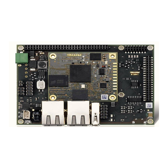
- Page 10 Wega AM335x 1.4 View of the phyBOARD-Wega-AM335x: © PHYTEC Embedded Pvt. Ltd. 2014...
-
Page 11: Pcl-051/Phycore-Am335X System On Module
The phyCORE-AM335x belongs to PHYTEC’s phyCORE System on Module (SOM) family. The phyCORE SOMs represent the continuous development of PHYTEC SOM technology. Like its mini-, micro-, and nano MODULE predecessors, the phyCORE boards integrate all core elements of a microcontroller system on a sub miniature board and are designed in a manner that ensures their easy expansion and embedding in peripheral hardware developments. -
Page 12: Accessing The Phyboard-Wega Interfaces
3. Accessing the phyBOARD-Wega Interfaces: PHYTEC phyBOARD-Wega is fully equipped with all mechanical and electrical components necessary speedy secure start-up subsequent communication to and programming of applicable PHYTEC System on Module (SOM) modules. phyBOARD-Wega Boards designed evaluation, testing and prototyping of PHYTEC System on Module in laboratory environments prior to their use in customer designed applications. - Page 13 As damage from improper connections varies according to use and application, it is the user‘s responsibility to take appropriate safety measures to ensure that the module connections are protected from overloading through connected peripherals. © PHYTEC Embedded Pvt. Ltd. 2014...
-
Page 14: Leds
A 5 V adapter with a minimum Supply of 1.5 A is recommended. © PHYTEC Embedded Pvt. Ltd. 2014... - Page 15 Do not confuse the USB Micro connector on the upper side of the board with the one on the back side of the board which provides USB OTG connectivity. The USB Micro connector on the upper side is exclusively used for power supply and has no other USB functionality! © PHYTEC Embedded Pvt. Ltd. 2014...
- Page 16 Wega. This voltage source supplies the backup voltage domain VBAT of the AM335x which supplies the RTC and some critical registers when the primary system power, VCC5V_IN, is removed. The backup supply lasts approximately. 5.4 RS-232 Connectivity (X66) RS-232 Interface Connector X66 © PHYTEC Embedded Pvt. Ltd. 2014...
- Page 17 HP Auto-MDIX technology, eliminating the need for the consideration of a direct connect LAN cable, or a cross-over path cable. They detect the TX and RX pins of the connected device and automatically configure the PHY TX and RX pins accordingly. © PHYTEC Embedded Pvt. Ltd. 2014...
- Page 18 McASP0 interface to support stereo line input and stereo line output at connector X73. In addition to that the phyBOARD-Wega has one direct mono speaker output (2 × 1 W) at the Molex connector X55. X55: Speaker Audio Interfaces at Connectors X55 and X73 X73:LINE IN LINEOUT © PHYTEC Embedded Pvt. Ltd. 2014...
- Page 19 The CAN1 interface of the phyBOARD-Wega-AM335x is accessible at connector X65 (2×5 2.54 mm pin header). Jumper JP3 can be installed to add a 120 Ohm termination resistor across the CAN data lines if needed. Components supporting the CAN Interface © PHYTEC Embedded Pvt. Ltd. 2014...
- Page 20 MMC cards. Power to the SD interface is supplied by inserting the appropriate card into the SD/MMC connector, who features a card detection, a lock mechanism and a smooth extraction function by Push-in /-out of card. “The AM335x processor on the phyBAORD-Wega can boot from this interface.” © PHYTEC Embedded Pvt. Ltd. 2014...
- Page 21 "The phyBOARD-Wega is equipped with a system reset button at S2. Pressing this button will toggle the X_nRESET_IN pin of the phyCORE SOM low, causing the module to reset. Additionally, a reset is generated on nRESET_OUT to reset peripherals." System Reset Button S2 © PHYTEC Embedded Pvt. Ltd. 2014...
-
Page 22: System Level Hardware Information
X_LCD_D8 LCD D8 X_LCD_D9 LCD D9 X_LCD_D10 LCD D10 Ground X_LCD_D23 LCD D23 X_LCD_D20 LCD D20 X_LCD_D17 X_LCD_D17 X_LCD_D11 LCD D11 Ground X_LCD_D12 LCD D12 X_LCD_D13 LCD D13 X_LCD_D14 LCD D14 X_LCD_D15 LCD D15 © PHYTEC Embedded Pvt. Ltd. 2014... - Page 23 A/V interrupt; GPIO1_30 X_MCASP0_AHCLK McASP0 high frequency clock Ground nRESET_OUT Reset TS_X+ Touch X+ TS_X- Touch X- TS_Y+ Touch Y+ TS_Y- Touch Y- VCC3V3 3.3 V power supply Ground X_I2C0_SCL I²C Clock X_I2C0_SDA I²C Data © PHYTEC Embedded Pvt. Ltd. 2014...
-
Page 24: Expansion Connector
JTAG Chain Test Data Output Ground X_JTAG_TCK JTAG Chain Test Clock signal X_USB1_DP_EXP USB1 data plus X_USB1_DM_EXP USB1 data minus nRESET_OUT Reset Ground X_MMC2_CMD MMC command X_MMC2_DAT0 MMC data 0 X_MMC2_CLK MMC clock X_MMC2_DAT1 MMC data 1 © PHYTEC Embedded Pvt. Ltd. 2014... - Page 25 USB1_VBUS USB 1 bus voltage X_USB1_CE USB 1 charger enable Ground X_PMIC_POWER_EN Enable Power Management IC for AM335x X_PB_POWER Power On for Power Management IC for AM335x Ground VCC5V_IN 5 V input supply voltage © PHYTEC Embedded Pvt. Ltd. 2014...
-
Page 26: Technical Specifications
2.05W typ.; Linux booted from Micro SD card, running ping test 9. Revision History Table 15. Revision History Date Version Number Changes in this Manual 08/11/2013 Hardware Manual Preliminary documentation. PBA-CD-03 Describes the phyBOARD-WEGA- AM335x With phyCORE-AM335x SOM. © PHYTEC Embedded Pvt. Ltd. 2014... -
Page 27: Placment Diagrams
10. PLACMENT DIAGRAMS Figure 16. Placement Diagram of phyBOARD-WEGA-AM335x Top Placement Diagram of phyBOARD-WEGA-AM335x © PHYTEC Embedded Pvt. Ltd. 2014... - Page 28 Bottom Placement Diagram of phyBOARD-WEGA-AM335x Note: If you want more information about mechanical dimensions please visit the this FTP link: ftp://ftp.phytec.de/pub/Products/phyBOARD-WEGA-AM335x/Layout/PL1397_0/ © PHYTEC Embedded Pvt. Ltd. 2014...
- Page 29 203 Parfitt Way SW, Suite G100 Bainbridge Island, WA 98110 Tel.: +1 206 780-9047 Fax: +1 206 780-9135 www.phytec.com France PHYTEC France SARL 17, place St. Etienne F-72140 Sillé le Guillaume Tel.: +33 2 43 29 22 33 © PHYTEC Embedded Pvt. Ltd. 2014...
Need help?
Do you have a question about the phyBOARD WEGA-AM335x and is the answer not in the manual?
Questions and answers