Table of Contents
Advertisement
Quick Links
KD-Pro8x8D
8x8 HDBaseT/HDMI/POH Matrix Switcher, Integrated
Audio, DSP/De-embedding of Analog L/R Balanced/
Unbalanced, Digital Coaxial Audio, ARC
(Includes 8 Rx Extenders- 6 Short & 2 Long Range)
Operating Instructions
x6
x2
KD-X88LGRx
KD-X88SHRx
The Experts in Digital Video Technology and Solutions
™
Advertisement
Table of Contents

Related Manuals for Key Digital KD-Pro8x8D


Summary of Contents for Key Digital KD-Pro8x8D
- Page 1 KD-Pro8x8D 8x8 HDBaseT/HDMI/POH Matrix Switcher, Integrated Audio, DSP/De-embedding of Analog L/R Balanced/ Unbalanced, Digital Coaxial Audio, ARC (Includes 8 Rx Extenders- 6 Short & 2 Long Range) Operating Instructions KD-X88LGRx KD-X88SHRx The Experts in Digital Video Technology and Solutions ™...
- Page 2 RS-232 and TCP/IP Commands ..........19 Using KD-Pro8x8D in a Compass Control® Pro project......25 Specifications .
- Page 3 36 ports to control system Control Integration: TCP/IP, RS-232, and USB with full bi-directional operation, front panel push › buttons and LEDs, front/rear optical IR, serial IR, Control System Support: Key Digital App ready, Compass Control Pro ready, KD-Wizard ®...
-
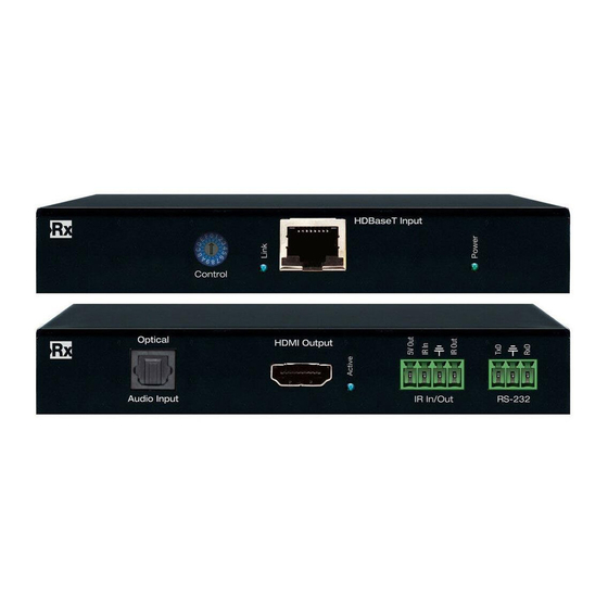
Page 4: About Kd-X88Shrx And Kd-X88Lgrx Hdbaset Receive Extenders
› Rack mount ears › Rack Mounting Secure the included rack ears to each side of KD-Pro8x8D with the supplied hardware, then › fasten the unit to the rack rails with appropriate machine screw. About KD-X88SHRx and KD-X88LGRx HDBaseT receive extenders Extends HDMI video + audio, and control (IR and RS-232) via a single CAT5e/6 UTP or STP cable ›... -
Page 5: Connections, Buttons And Leds
Connections, Buttons and LEDs HDMI & HDBaseT HDMI Inputs (8): Located on the left side of the back panel. The inputs have a blue LED that › illuminates when a source is connected and synced HDMI & HDBaseT Outputs (8 each): Located in the middle of the back panel. The HDMI and ›... - Page 6 Pin 6 = Ground (optional) » TCP/IP Control Port › Connect an Ethernet cable from the KD-Pro8x8D to a network router or connect a straight- » through cable directly from a PC Default IP address is 192.168.1.239, with default port 23 »...
- Page 7 Control I/O Ports 8 multifunction I/O ports that can be used as IR, bi-directional RS-232 or voltage trigger › Pin out: » Pin 1 = RS-232 TxD / IR Signal » Pin 2 = Ground » Pin 3 = RS-232 RxD / IR No Connect »...
-
Page 8: Kd-X88Shrx And Kd-X88Lgrx Led Indicator Lights
Buttons and LEDs 8 output buttons on the front panel › Pressing an output button will select the next HDMI input » A blue LED indicates selected input for each output » Video output MUTE is indicated by the outermost (1, 2, 7, 8) LEDs illuminated, ›... -
Page 9: Application Example
Mount Vernon NY 10553 phone: 914.667.9700 ext 3 • • Supports iOS & Android phone: 914.667.9700 fax: 914.668.8666 www.keydigital.com/compass • RS232 HDMI KD-Pro8x8D Media Server RS232 HDMI RJ45 Office PCs HDMI Main Huddle - Mirrored Displays 1-8 HDMI KD-AMP220 HDMI Line... -
Page 10: Quick Setup Guide
Quick Setup Guide 1. Begin with the KD-Pro8x8D and all input/output devices turned off and power cables removed 2. Connect HDMI sources to the desired input ports on the KD-Pro8x8D 3. Connect HDBaseT outputs to the Rx extenders via CAT5e/6 cables 4. - Page 11 Default EDID Table HDMI Video 1080i@60, Audio 2CH PCM HDMI Video 1080i@60, Audio PCM,DTS/DOLBY 5.1 HDMI Video 1080i@60, Audio PCM,DTS/DOLBY/HD 7.1 HDMI Video 1080p@60, Audio 2CH PCM HDMI Video 1080p@60, Audio PCM,DTS/DOLBY 5.1 HDMI Video 1080p@60, Audio PCM,DTS/DOLBY/HD 7.1 HDMI Video 4Kx2K@24/30, Audio 2CH PCM HDMI Video 4Kx2K@24/30, Audio PCM,DTS/DOLBY 5.1 HDMI Video 4Kx2K@24/30, Audio PCM,DTS/DOLBY/HD 7.1 HDMI Video 4Kx2K@50/60(4:2:0), Audio 2CH PCM...
- Page 12 Volume and Muting Control Set Output XX to Audio Volume YY [00-99] › IR Button Sequence = R1, XX, Volume, YY » Set Output XX Audio Volume Up › Power On IR Button Sequence = R1, XX, Volume, UP » Power Off Set Output XX Audio Volume Down ›...
-
Page 13: Kd-X88Lgrx Control Rotary
Extends 1080p signals up to 500 ft. (152m). If Long Range mode is enabled, UHD/4K signals are not supported The desired setting for Long Range Mode must be applied on the Rx unit and to the desired KD-Pro8x8D outputs (1 or 5 only) Long Range Mode OFF: ›... - Page 14 Optical Rx Bypass Long Range Pass-through HDMI Optical Rx Standard Pass-through HDMI Optical Rx Long Range Pass-through HDMI Bypass Standard Rx unit HDBaseT F/W Upgrade HDMI Bypass Long Range Rx unit HDBaseT F/W Upgrade HDMI Forced HPD Standard Rx unit HDBaseT F/W Upgrade HDMI...
-
Page 15: Audio Return Channel (Arc)
Audio Return Channel (ARC) KD-Pro8x8D supports Audio Return Channel. When enabled, audio from the connected display is returned to the matrix and output on KD-Pro8x8D’s audio de-embed ports. ARC is useful in applications where an internet-enabled display is streaming content. ARC is a means for the audio to still reach the distributed audio system or AV Receiver. -
Page 16: Ir & Rs-232 Control Routing Ports And Uses
IR & RS-232 Control Routing Ports and Uses KD-Pro8x8D can pass-thru or route control signals just like it can HDMI signals. Control Connections and Signals 8x HDBaseT Rx › 9x Control I/O on matrix › Port 9 is recommend as the primary IR/RS-232 input source for control routing »... - Page 17 Each IR and RS-232 port is bi-directional, allowing for control signal flow from the matrix (source) › to the zone (destination) or from the zone to the matrix. When connecting the IR Emitter to the device you wish to control make sure to find the IR receiver ›...
- Page 18 Control Routing Commands Control routes may be established via RS-232 and TCP/IP › Point-to-point routing will disconnect any existing destination(s) for source yy › Point-to-many routing will add destination(s) for source xx without disconnecting other › destinations Point-to-Point IR Control Routing: To configure the path of IR control signals from an Control I/O Port to an HDBaseT output, ›...
- Page 19 Point-to-Many RS-232 Control Routing To configure the path of RS-232 control signals from an Control I/O Port to multiple HDBaseT › outputs, use the command SPOC xx RS 1 S yy xx=RS-232 destination, yy=RS-232 source » Send additional SPOC xx RS 1 S yy commands for each additional destination »...
- Page 20 Audio Output Setup Set Output XX Audio Volume to YY, YY=[00-99] R1, XX, Volume, YY Set Output XX Audio Volume Up R1, XX, Volume, UP Set Output XX Audio Volume Down R1, XX, Volume, DOWN Set Output XX Audio Balance to YY, YY=[00-40],U,D R1, XX, Balance, YY/UP/DOWN Set Output XX Audio Bass Freq.
-
Page 21: Rs-232 And Tcp/Ip Commands
RS-232 and TCP/IP Commands KD-Pro8x8D allows control over serial interface for bi-directional communication. Use pins 3, 4, 5 for RS-232 communication. In addition to RS-232, the serial interface may also be accessed using a TCP/IP connection Default IP address is 192.168.1.239, with default port 23 »... - Page 22 -- SPC PWRST hh:mm : Set Power Reset Time by hh=[00~23], mm=[00~59] -- SPCDF : Factory Default without EDID change -- SPCDF zz : Factory Default, zz=[01-15](DEFAULT EDID 01-15) -- System Control Setup Commands: -- Network Setup, xxx = [000-255], zzzz = [0001-4999] -- SPC ETIPA xxx.xxx.xxx.xxx : Set Host IP Address to xxx.xxx.xxx.xxx -- SPC ETIPM xxx.xxx.xxx.xxx : Set Net Mask to xxx.xxx.xxx.xxx -- SPC ETIPR xxx.xxx.xxx.xxx : Set Route IP Address to xxx.xxx.xxx.xxx --...
- Page 23 -- SPOC xx RS z S yy : Set from yy of z to CAT5e/6 Output(RS232) xx -- SPOC xx RSS z S yy : Route from yy of z to CAT5e/6 Output(RS232) xx -- -- SPE xx IR z S yy : Set from yy of z to Expantion I/O(IR) xx -- SPE xx IRR z S yy : Route from yy of z to Expansion I/O(IR) xx -- SPE xx RS z S yy...
- Page 24 Status Command (STA) – Returns unit and system status in readable format: KD-Pro8x8D> STA ------------------------------------------------------------------------- Key Digital Systems : KD-Pro8x8D Status ------------------------------------------------------------------------- Unit Name : UN000042 F/W Version : 1.02 -- System Address : 00, Time : 01:11:42 -- Power : ON ,...
- Page 25 -- Video Output Status ------------------------------------------------------------------------- -- 01: Input = 01, Mode = AUTO(DVI ,DVI ), VM = UNMUTED, Output = ON HDMI= NONE , HPD = OFF, Link = OFF, HDCP = NONE , DDC = GOOD -- Control I/O TYPE = IR , SRC = None CAT5= NONE , HPD = OFF, Link = OFF, HDCP = NONE...
- Page 26 -- Audio Output DSP Status -- 01: IN=HDMI, V=90, B=20, L=12, M=12, T=12, LP=00, MUTE=DISABLE -- 02: IN=HDMI, V=90, B=20, L=12, M=12, T=12, LP=00, MUTE=DISABLE -- 03: IN=HDMI, V=90, B=20, L=12, M=12, T=12, LP=00, MUTE=DISABLE -- 04: IN=HDMI, V=90, B=20, L=12, M=12, T=12, LP=00, MUTE=DISABLE -- 05: IN=HDMI, V=90, B=20, L=12, M=12, T=12, LP=00, MUTE=DISABLE -- 06: IN=HDMI, V=90, B=20, L=12, M=12, T=12, LP=00, MUTE=DISABLE -- 07: IN=HDMI, V=90, B=20, L=12, M=12, T=12, LP=00, MUTE=DISABLE...
- Page 27 Using KD-Pro8x8D in a Compass Control Pro project ® 1. Choose your all-in-one matrix + MC in the Setup Controllers step. Add IP address, which must match IP address configured to matrix 2. In the Controlling Flow step, drag the MC from the Devices Library to the Master...
- Page 28 3. Drag desired devices from Devices Library to available MC ports. Displays connected via HDBaseT Rx are typically dragged to the ports labelled CAT5Output_1-8 4. Source and other in-rack equipment are typically controlled on the Expansion I/O Ports of the matrix MC.
-
Page 29: Specifications
Specifications Technical: Input (Each): 1 HDMI Connector, Type A, 19 Pin Female » Output (Each): 1 HDMI Connector, Type A, 19 Pin Female; 1 HDBaseT, CAT5e/6 on RJ45 » connector; 6-Pin Terminal Block for Analog L/R Output; RCA Jack for Digital Audio Output [follows SPDIF format (IEC 60958 )] Control I/O (Each): 6-Pin Terminal Block configured as IR or RS-232 with variable voltage »... -
Page 30: Important Product Warnings
Damage to the power supply or power plug » Exposure to rain or moisture » Power Supply Use: You MUST use the Power Supply provided with your unit or you VOID the Key Digital Warranty and risk damage to your unit and associated equipment. ®... -
Page 31: How To Contact Key Digital
Please email any comments/questions about the manual to: E-mail: customersupport@keydigital.com › Warranty Information All Key Digital products are built to high manufacturing standards and should provide years of ® trouble-free operation. They are backed by a Key Digital Limited 3 Year Product Warranty Policy. http://www.keydigital.com/warranty.htm... - Page 32 , led by digital video pioneer Mike Tsinberg, ® develops and manufactures high quality, cutting-edge technology solutions for virtually all applications where high-end video and control are important. Key Digital ® is at the forefront of the video industry for Home Theater Retailers, Custom Installers, System Integrators, Broadcasters, Manufacturers, and Consumers.
Need help?
Do you have a question about the KD-Pro8x8D and is the answer not in the manual?
Questions and answers