Emotron VS30 Series Mounting And Switch On Instruction
Ac drive
Hide thumbs
Also See for VS30 Series:
- Instruction (34 pages) ,
- Operation instructions manual (528 pages)
Table of Contents
Advertisement
Quick Links
Advertisement
Table of Contents

Subscribe to Our Youtube Channel
Related Manuals for Emotron VS30 Series


Summary of Contents for Emotron VS30 Series
- Page 1 Emotron VS30 AC drive 3 … 7.5 kW Mounting and switch on instruction...
- Page 2 This page intentionally left blank!
-
Page 3: Table Of Contents
Contents Contents 1 General information 1.1 First read, then start 1.2 Notations and conventions 1.2.1 Product code 2 Safety instructions 2.1 Basic safety measures 2.2 Residual hazards 2.3 Application as directed 3 Product description 4 Mounting 4.1 Important notes 4.2 Mechanical installation 4.3 Electrical installation 4.3.1 Connection to the 400 V system... - Page 4 This page intentionally left blank!
-
Page 5: General Information
First read, then start Read this documentation thoroughly before carrying out the installation and commissioning. Please observe the safety instructions! Information and tools with regard to the Emotron products can be found on the Internet: http://www.emotron.com/services-support/file-archive Notations and conventions 1.2.1... -
Page 6: Safety Instructions
The procedural notes and circuit details described in this document are only proposals. It is up to the user to check whether they can be adapted to the particular applications. Emotron does not take any responsibility for the suitability of the procedures and circuit proposals described. -
Page 7: Residual Hazards
Safety instructions Residual hazards Residual hazards The user must take the residual hazards mentioned into consideration in the risk assessment for his/her machine/system. If the above is disregarded, this can lead to severe injuries to persons and damage to material assets! Product Observe the warning labels on the product! Description... -
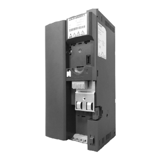
Page 8: Product Description
Product description Product description Mains connection X100 PE connection Relay output X9 Network X2xx Option Network status LEDs DIP switch Baud rate and bus adress Interface X16 (CANopen/Modbus) Diagnostic module Inverter status LEDs Memory moodule X20 Control terminals X3 Standard I/O or Application I/O Shield connection Control connections IT screw... -
Page 9: Mounting
Mounting Important notes Mounting Important notes DANGER! Dangerous electrical voltage Possible consequence: death or severe injuries ▶ All works on the inverter must only be carried out in the deenergised state. ▶ After switching off the mains voltage, wait for at least 3 minutes before you start working. -
Page 10: Mechanical Installation
Mounting Mechanical installation Mechanical installation Dimensions 3 kW ... 5,5 kW All Dimensions in mm... - Page 11 Mounting Mechanical installation Dimensions 7,5 kW All Dimensions in mm...
-
Page 12: Electrical Installation
Mounting Electrical installation Connection to the 400 V system Electrical installation 4.3.1 Connection to the 400 V system 4.3.1.1 Connection plan Fig. 1: Wiring example Start enable Dashed line = options... -
Page 13: Fuses And Cable Cross-Sections
Mounting Electrical installation Connection to the 400 V system 4.3.1.2 Fuses and cable cross-sections Operation without mains choke Cable installation in compliance with EN 60204-1 Laying system Inverter VS30407P3 VS30409P5 VS3040013 VS3040016 Rated power Rated mains current without mains choke 12,5 17,2 Fuse... - Page 14 Mounting Electrical installation Connection to the 400 V system PE conductor connection Inverter VS30407P3 VS30409P5 VS3040013 VS3040016 Rated power Connection Connection type PE screw Min. cable cross-section mm² Max. cable cross-section mm² Stripping length Tightening torque Required screwdriver 0.8 x 5.5 Control connections Terminal description Relay output...
-
Page 15: Connection To The It System
Mounting Electrical installation CANopen connection 4.3.2 Connection to the IT system NOTICE! Internal components have earth potential if the IT screws are not removed. Consequence: the monitoring functions of the IT system respond. ▶ Before connection to an IT system be absolutely sure to remove the IT screws. TX10 TX10... -
Page 16: Canopen Connection
Node address - example: aktiv 250 kbps OF OFF ON Value from parameter (500 Node address = 16 + 4 + 2 + 1 = 23 kbps) 1 Mbps All other Value from combinations parameter (500 kbps) Printed in bold = Emotron setting... -
Page 17: Modbus Connection
Automatic Value from parameter Node address - example: Active Value from parameter Value from parameter Node address = 16 + 4 + 2 + 1 = 23 Node address > 247: value from parameter Printed in bold = Emotron setting... -
Page 18: Connection Of The Safety Module
Mounting Electrical installation Connection of the safety module 4.3.5 Connection of the safety module 4.3.5.1 Important notes DANGER! Improper installation of the safety engineering system can cause an uncontrolled starting action of the drives. Possible consequences: Death or severe injuries ▶... -
Page 19: Connection Plan
Mounting Electrical installation Connection of the safety module 4.3.5.2 Connection plan Passive sensors Active sensors safety switching device active sensor - example lightgrid passive sensor 4.3.5.3 Terminal data Terminal description Safety STO Connection Connection type Screw terminal Min. cable cross-section mm²... -
Page 20: Commissioning
Commissioning Important notes Commissioning Important notes WARNING! Incorrect settings during commissioning may cause unexpected and dangerous motor and system movements. Possible consequence: death, severe injuries or damage to material assets ▶ Clear hazardous area. ▶ Observe safety instructions and safety clearances. Before initial switch-on Prevent injury to persons and damage to material assets. -
Page 21: Initial Switch-On / Functional Test
Target: achieve rotation of the motor connected to the inverter as quickly as possible. Requirements: • The connected motor matches the inverter in terms of power. • The parameter settings comply with the delivery status (Emotron setting). 1. Preparation: 1. Wiring of power terminals. (Chapter 4.3 Electrical installation) 2. - Page 22 2. Inhibit inverter again: X3/DI1 = LOW. The functional test is completed. The commissioning process of the drive solution is described in a separate commissioning instruc- tion which can be found on the Internet in our download area: http://www.emotron.com/ services-support/file-archive/...
-
Page 23: Technical Data
Technical data Standards and operating conditions Technical data Standards and operating conditions Conformities 2014/35/EU Low-Voltage Directive 2014/30/EU EMC Directive (reference: CE-typical drive system) TR TC 004/2011 Eurasian conformity: Safety of low voltage equipment TP TC 020/2011 Eurasian conformity: Electromagnetic compatibility of technical means RoHS 2 2011/65/EU... - Page 24 Technical data Standards and operating conditions Requirements to the shielded motor cable Capacitance per unit length C-core-core/C-core-shield < 75/150 ≤ 2,5 mm² / AWG 14 pF/m C-core-core/C-core-shield < 150/300 ≥ 4 mm² / AWG 12 pF/m Electric strength Uo/U = 0,6/1,0 kV Uo = r.m.s.
-
Page 25: Rated Data
Technical data Rated data Connection to the 400 V system Rated data 6.2.1 Connection to the 400 V system Inverter I55AE230F I55AE240F I55AE255F I55AE275F Rated power Mains voltage range 3/N/PE AC 360 V ... 440 V, 45 Hz ... 55 Hz Operating mode Max. - Page 26 ©12/2015 | 13506330 | 2.0 / 01-6211-01r2 CG DRIVES & AUTOMATION Mörsaregatan 12, Box 222 25 SE- 250 24 Helsingborg, Sweden +46 42 16 99 00 Info: info.se@cgglobal.com Order: order.se@cgglobal.com...
Need help?
Do you have a question about the VS30 Series and is the answer not in the manual?
Questions and answers