Hilti PR 30-HVSG A12 Operating Instructions Manual
Hide thumbs
Also See for PR 30-HVSG A12:
- Operating instructions manual (448 pages) ,
- Original operating instructions (96 pages) ,
- Manual (434 pages)
Table of Contents
Advertisement
Advertisement
Table of Contents

Related Manuals for Hilti PR 30-HVSG A12


Summary of Contents for Hilti PR 30-HVSG A12
- Page 1 PR 30-HVSG English Printed: 29.09.2017 | Doc-Nr: PUB / 5376998 / 000 / 00...
- Page 2 Printed: 29.09.2017 | Doc-Nr: PUB / 5376998 / 000 / 00...
- Page 3 Do not look straight into the laser beam. 1.4 Product information Hilti products are designed for professional use and may be operated, serviced and maintained only by trained, authorized personnel. This personnel must be informed of any particular hazards that may be encountered.
- Page 4 ▶ Take the influences of the surrounding area into account. Do not use the device where there is a risk of fire or explosion. ▶ Statement in accordance with FCC §15.21: Changes or modifications not expressly approved by Hilti can restrict the user’s authorization to operate the equipment.
- Page 5 ▶ Use of the telescopic staff in the vicinity of overhead high voltage cables is not permissible. 2.4 Electromagnetic compatibility Although the tool complies with the strict requirements of the applicable directives, Hilti cannot exclude the following possibilities: •...
- Page 6 ▶ Do not charge or continue to use damaged batteries (e.g. batteries with cracks, broken parts, bent or pushed-in and/or pulled-out contacts). ▶ Recharge only with the charger specified by the manufacturer. A charger that is suitable for a certain type of battery may present a risk of fire when used with other types of battery.
- Page 7 English Printed: 29.09.2017 | Doc-Nr: PUB / 5376998 / 000 / 00...
- Page 8 English Printed: 29.09.2017 | Doc-Nr: PUB / 5376998 / 000 / 00...
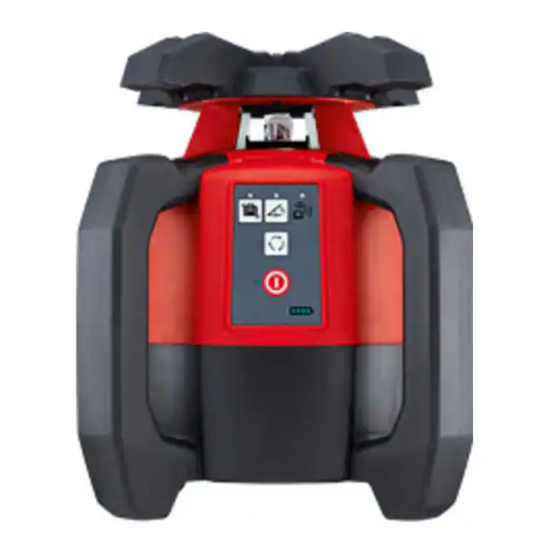
- Page 9 3 Description 3.1 Product overview 3.1.1 PR 30-HVSG A12 rotating laser English Printed: 29.09.2017 | Doc-Nr: PUB / 5376998 / 000 / 00...
- Page 10 Control panel Grip Base plate with 5/8" thread § Battery release button & 3.1.2 PR 30-HVSG A12 control panel Inclined plane mode button and LED On/off button & Shock warning function button and LED Surveillance mode LED (only with auto-...
- Page 11 The tool is designed to be used to determine, transfer and check levels, verticals, slopes and right angles. ▶ Use only the Hilti B 12⁄2.6 Li-Ion battery for this product. ▶ Use only the Hilti C 4⁄1250 charger for this product.
- Page 12 3.11 Laser receiver / remote control unit Hilti laser receivers digitally indicate the distance between the marking notch on the laser receiver and the position at which the laser beam (laser plane) strikes the detection area on the receiver. The laser beam can also be received over long distances.
- Page 13 3.15 Items supplied PR 30-HVSG A12 rotating laser, PRA 30G laser receiver / remote control unit, 2 batteries (AA cells), PRA 54 target plate, operating instructions. Other system products approved for use with this product can be found at your local Hilti Store or online at: www.hilti.group.
- Page 14 The B12 battery has no protection class. Do not expose the battery to rain or wet conditions. In accordance with the Hilti instructions, the battery may be used only with the associated product and must be inserted in the battery compartment for this purpose.
- Page 15 5.3 Inserting / removing the battery CAUTION Electrical hazard. Dirty contacts may cause a short circuit. ▶ Check that the contacts on the battery and on the tool are free from foreign objects before inserting the battery. CAUTION Risk of injury. If the battery is not fitted correctly it may drop out and fall. ▶...
- Page 16 ◁ As soon as the tool has leveled itself, the laser beam switches on and begins to rotate and the "auto leveling" LED shows steadily. Note A wall bracket or tripod may be used as mounting devices. The angle of inclination of the surface on which it stands should not exceed ±...
- Page 17 1. Press the button on the rotating laser, on the PRA 30G laser receiver and on the PRA 90 automatic tripod. ◁ The devices are ready for use. 2. Keep the marking notch on the PRA 30G laser receiver at the height that is to be set. The PRA 30G laser receiver should be held steady or secured in place.
- Page 18 1. Press the button on the rotating laser. ◁ The rotating laser levels itself and then projects a stationary downward-pointing laser beam. 2. Position the rotating laser so that the projected laser beam strikes reference point (A) exactly. Please note: The reference point is not a plumb point! 3.
- Page 19 ◁ The rotating laser levels itself once the position has been reached. The symbol is displayed briefly. ▽ If automatic alignment cannot be completed successfully, short signal tones are emitted and the is displayed briefly. 5. Double-click the button on the PRA 30G laser receiver. ◁...
- Page 20 1. Position the rotating laser either at the upper edge or lower edge of the inclined plane. 2. Use the target sight on the head of the tool to align the rotating laser parallel to the inclined plane. 3. Press the button on the rotating laser and the PRA 30G laser receiver.
- Page 21 5.12 Setting inclination automatically Note The rotating laser, depending on the application, is mounted or positioned securely. The PRA 30G laser receiver and the rotating laser are paired. The PRA 30G laser receiver and the receiving side of the rotating laser are facing each other and in direct line of sight.
- Page 22 5.14 Automatic scan line function 1. Press the button on the rotating laser. 2. Adjust the laser plane to the desired position / height. The scan line function can be used in horizontal, vertical and inclined plane mode. 3. Press the button on the PRA 30G to display the AUTO menu.
- Page 23 2. Switch the devices on again. 6.3 Pairing the PRA 90 tripod and the PRA 30G laser receiver 1. Position both tools at a distance of about 0.5 m from each other. Press the button on both devices for at least 3 seconds. ◁...
- Page 24 Point Speed of rotation menu 300 revolutions per minute 600 revolutions per minute 1200 revolutions per minute Rotating laser settings menu Sleep mode Shock warning Switch off beam segments Shock warning submenu Level 1, high sensitivity Level 2, medium sensitivity Level 3, low sensitivity Sleep mode submenu Sleep mode on...
- Page 25 2 mm 5 mm 10 mm 25 mm Menu information Software versions Service deadline QR code AUTO menu Press the button once to open the AUTO menu. Automatic alignment Automatic alignment with surveillance function Automatic scan line function 6.6 PRA 83 laser receiver with holder 1.
- Page 26 3. Fit the rubber sleeve onto the magnetic grip piece. 4. Press the button. 5. Unscrew the clamping knob on the grip piece slightly. 6. Mount the PRA 83 laser receiver on a telescopic staff or leveling staff and secure it by tightening the clamping knob.
- Page 27 6.8 PRA 81 laser receiver with holder 1. Open the retainer on the PRA 81 and insert the laser receiver. 2. Close the retainer on the PRA 81. 3. Press the button. 4. Hold the laser receiver with the receiving window directly in the plane of the laser beam. 5.
- Page 28 Observe the temperature limits when drying the equipment. 7.2 Hilti Measuring Systems Service Hilti Measuring Systems Service checks the product and, if deviations from the specified accuracy are found, recalibrates it and checks it again to ensure conformity with specifications. The service certificate provides written confirmation of conformity with specifications at the time of the test.
- Page 29 When this procedure is carried out carefully, the vertical distance between the two marked points 1 and 3 (main axis) or, respectively, points 2 and 4 (transverse axis) should be less than 2 mm (at 20 m). If the deviation is greater than this, please return the tool to Hilti Service for calibration. English...
- Page 30 ◁ When this procedure is carried out carefully, the horizontal distance between the two marked points (B) and (C) should be < 2 mm (at 10 m). If the deviation is greater than this, return the device to Hilti Service for calibration.
- Page 31 9 Troubleshooting If the trouble you are experiencing is not listed in this table or you are unable to remedy the problem by yourself, please contact Hilti Service. Trouble or fault Possible cause Action to be taken The tool doesn’t work.
- Page 32 Trouble or fault Possible cause Action to be taken The laser is too steeply inclined, ▶ Bring the laser into an upright leveling not possible. position as far as possible. ▶ Switch the rotating laser on. → page 13 Laser position warning. The laser receiver is outside the ▶...
- Page 33 Most of the materials from which Hilti tools and appliances are manufactured can be recycled. The materials must be correctly separated before they can be recycled. In many countries, your old tools, machines or appliances can be returned to Hilti for recycling. Ask Hilti Service or your Hilti representative for further information.
- Page 34 English Printed: 29.09.2017 | Doc-Nr: PUB / 5376998 / 000 / 00...
- Page 35 Printed: 29.09.2017 | Doc-Nr: PUB / 5376998 / 000 / 00...
- Page 36 Printed: 29.09.2017 | Doc-Nr: PUB / 5376998 / 000 / 00...
- Page 37 Printed: 29.09.2017 | Doc-Nr: PUB / 5376998 / 000 / 00...
- Page 38 Hilti = registered trademark of Hilti Corp., Schaan 20170926 Printed: 29.09.2017 | Doc-Nr: PUB / 5376998 / 000 / 00...
Need help?
Do you have a question about the PR 30-HVSG A12 and is the answer not in the manual?
Questions and answers