Table of Contents
Advertisement
Quick Links
Advertisement
Table of Contents

Related Manuals for AUDAC AMP523MK2


Summary of Contents for AUDAC AMP523MK2
-
Page 1: User Manual
AMP523 User Manual www.audac.eu... - Page 3 Index Introduction Precautions Safety requirements Caution servicing EC Declaration of Conformity Waste of Electrical and Electronic Equipment (WEEE) Chapter 1: Connections and connectors Connection standards Chapter 2: Overview AMP523 Front panel Rear panel Block diagram Chapter 3: AMP523 Quick start guide Connecting the AMP523 Configuring the AMP523 Chapter 4: User interface &...
- Page 5 Introduction Web-based mini stereo amplifier The AMP523MK2 is a mini stereo amplifier with an integrated web based control unit featuring four stereo line inputs and one balanced microphone input with phantom po- wer. It has an output power of 2 x 15 Watt.
- Page 6 Precautions READ FOLLOWING INSTRUCTIONS FOR YOUR OWN SAFETY • ALWAYS KEEP THESE INSTRUCTIONS FOR FUTURE REFERENCE. NEVER THROW THEM AWAY • ALWAYS HANDLE THIS UNIT WITH CARE • CLEAN ONLY WITH DRY CLOTH • HEED ALL WARNINGS AND FOLLOW ALL INSTRUCTIONS •...
- Page 7 CAUTION • USE CABLES OF THE RIGHT GAUGE FOR CONNECTING LOUDSPEAKERS TO THE AMPLIFIED OUTPUTS • USE CABLES WITH CLEAR COLOUR CODING INDICATING THE POLARITY AND MAINTAIN THE SAME POLARITY THROUGHOUT THE WHOLE SYSTEM. • ONLY USE THE CORRECT LOAD IMPEDANCE (MIN 4 OHM) WHEN CONNECTING LOUDSPEAKERS TO THE AMPLIFIED OUTPUTS.
- Page 9 Chapter 1 Connections and connectors CONNECTION STANDARDS The in- and output connections for AUDAC audio equipment are performed corresponding to international wiring standards for professional audio equipment. RCA: For unbalanced line input connections Tip: Signal Sleeve: Ground White: Left Red:...
- Page 10 8 Bit 1 Stop bit No parity No Handshaking RS232 & TCP/IP The AMP523MK2 RS232 and TCP/IP ports accept the same commands. The complete command set is available in the AMP523MK2 commands user manual which is freely available on www.audac.eu...
-
Page 11: Front Panel
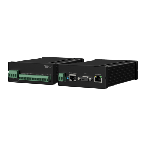
Overview AMP523 Front panel The front panel of the AMP523MK2 contains the audio in- and output connections. The available inputs are 4 unbalanced line-level inputs and one balanced microphone input (with phantom power). These all are performed using an 18-pins terminal block connector (combined with the line-level audio output). -
Page 12: Rear Panel
Rear panel All the control and configuration ports are located on the rear panel of the AMP523MK2, including the 24 Volts power connection. 1) 24 Volts power connector: The 24 Volts power supply connection is provided on the left side of the AMP523 MK2’s rear panel. - Page 13 Block diagram...
- Page 14 Connect all your audio sources (CD-players, tuners, mp3 players, microphones, ... ) to the audio inputs of the AMP523MK2. All the direct audio inputs are connected through the 18-pins terminal block. The pin layout for the 18-pins connector is shown at the front panel overview at page 11 of this user manual.
- Page 15 “Network Settings”. Now the IP address can get changed. Click OK to apply the changes and save. Afterwards, your browser will be automatically redirected to the new IP address of the AMP523MK2, and the default IP address is not longer valid. 2) Changing the password...
-
Page 16: Login Screen
Chapter 4 User interface & configuration To get access to the control and configuration settings, the AMP523MK2 should be connected to a computer or an Ethernet LAN network. For more information about network connections and settings, see IP basics in chapter 6. -
Page 17: Main Screen
After the correct password has been entered, the main screen of the user interface will be loaded and indicated as shown below. Main screen for AMP523MK2 This window shows the selection buttons for all 5 inputs (CH1 - CH4 and WLI-WMI/ MIC) combined with a mute button in the center position. - Page 18 The top right corner indicates a setup button which redirects you to the general configuration menu of the AMP523MK2. Save Use the ‘Save’ button in the top right corner when made any changes to the main screen configuration. Default configuration will be re-loaded when rebooting the AMP523MK2, if not saved.
-
Page 19: Configuration Screen
The settings control panel comes up after clicking the “Setup” button in the top right corner of the main screen. In this window, all settings for the AMP523MK2 can be configured, including network setttings, wall panel address settings (optional), input gain, phantom power and priority for the microphone input and password settings. -
Page 20: Network Settings
Configuration >> Network settings This window allows you to adjust the network settings of the AMP523MK2. The IP address is default set to 192.168.0.193 and the subnetmask is default set to 255.255.255.0. The settings can be changed by adjusting the parameters in the shown fields. -
Page 21: Wall Panel Settings
Set Address AMP523MK2 Connect the MWX45 wall panel to the “RS485 + AUDIO” RJ45 input on the AMP523MK2. Once connected, press the ‘Set address’ button on the wall panel settings menu. The message ‘Push the upper button on the wall panel to confirm the address’ will appear and the LED’s on the wall panel will start blinking. -
Page 22: Input Settings
The configured wall panel can be used for controlling the input routing on the AMP523MK2. In default configuration, all channels are selected. If not all inputs shall be selectable through the wall panel, the corresponding input can be disabled from the wall panel by selecting the ‘Off’... -
Page 23: Priority Settings
Input gain The left side shows all input channels combined with a dropdown list whereby the input gain can get adjusted. Default gain for every input is set to 0 dB. It can be adjusted within a range of -4 dB and +10 dB, in steps of 2 dB. This is done by clicking the dropdown list and selecting the desired gain adjustment factor. - Page 24 Priority settings screen for AMP523MK2 Enabled The priority can be enabled by clicking the “Enabled” button on top. This button will turn green when priority is enabled. Sensitivity The sensitivity for the priority channel can be put on “High”, “Medium” or “Low”. Hereby, the trigger level for switching to the priority channel can be set.
-
Page 25: Password Settings
Click the “Back” button to return back to the settings screen. Configuration >> Password settings In this window the password for the AMP523MK2 can be changed. Password settings screen for AMP523MK2 To change the password, enter the old password in the provided field and enter the new password twice in the fields below. -
Page 26: Factory Settings
BE CAREFUL to press this button. It really will recall the ORIGINAL factory settings !!! It does not recall the previously saved settings, but it recalls the original factory setting and the previously made settings will be lost. Click the “OK” button to reset the settings to factory default. Factory settings screen for AMP523MK2... - Page 27 Chapter 5 Peripheral connections In addition to the direct line and microphone inputs on the AMP523MK2, additional wall line and microphone inputs can be connected. It provides the possibility for connecting one additional wall line input unit (WLI) and one additional wall microphone input unit (WMI).
-
Page 28: Additional Information
Many AUDAC products are controllable by Ethernet. The Ethernet connection which is used on the AUDAC products is TCP/IP based, like 99% of the computer networks. There are some basics which you need to know to successfully make a TCP/IP Ethernet connection. - Page 29 This can be done in the settings menu, and is described extensively in the “Settings” chapter of this user manual. Of course, to make changes to the settings menu of the AUDAC products, you need to have access to the user interface on the product’s webpage. This can be done by temporarily giving your computer an IP address within the IP range of the AUDAC product, for example “192.168.0.193”.
-
Page 30: Technical Specifications
Chapter 4 Technical specifications 4 x Stereo balanced line Inputs Type Connectors 12-pin terminal block ~ 3.81 mm Impedance 20 k Ohm Sensitivity - 10 dBV ~ + 4dBV Balanced microphone Type Connectors 3-pin terminal block ~ 3.81 mm Impedance 47 k Ohm Sensitivity - 34 dBV ~ -18 dBV... - Page 31 Power supply 24V DC PSD241 switching power supply included 100 ~ 240V AC / 47~63 Hz Cooling Passive Protection Over-Heat Short circuit Limiter NOTE: ‘MUP’ stands for Maximum Undistorted Power Dimensions (W x H x D) 108 x 44 x 164 mm Weight 0.40 Kg Packaging...
- Page 32 Notes...
Need help?
Do you have a question about the AMP523MK2 and is the answer not in the manual?
Questions and answers