
Subscribe to Our Youtube Channel
Related Manuals for Teka EFX 30 1G AI AL TR 5kW


Summary of Contents for Teka EFX 30 1G AI AL TR 5kW
- Page 1 Instructions for the installation and advice for the maintenance EFX 30 1G AI AL TR 5 W - EFX 30 2G AI AL Instructions Manual EFX 30 1G AI AL TR 5 W - EFX 30 2G AI AL COD. 04041LT (Taiwan) - 04.03.2015...
-
Page 2: Description Of The Cooktop
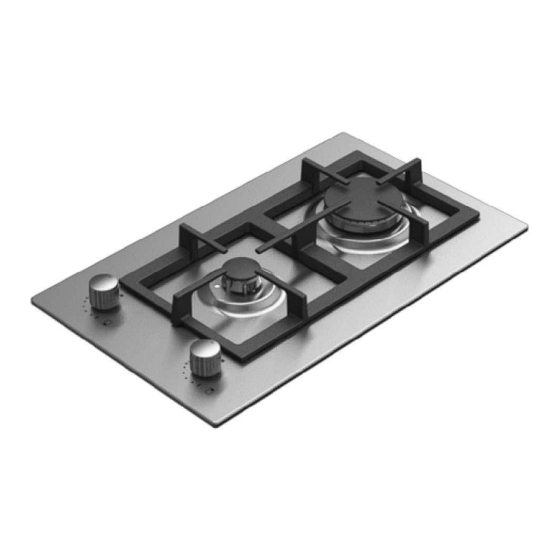
DESCRIPTION OF THE COOKTOP PCZJ 30 Model: EFX 30 1G AI AL TR 5kW Model: EFX 30 2G AI AL 1 Triple Ring (Wok) of 5000 W 2 Rapid burner of 3000 W 4 Auxiliary gas burner of 1000 W... - Page 3 DESCRIPTION OF THE COOKTOP 1) BURNERS Power Pan Ø Burners A diagram is screen-printed above each knob on ratings (W) in cm the front panel. This diagram indicates to which burner the knob in question corresponds. After Triple crown 5000 24 ÷...
- Page 4 WARNINGS AND ADVICE FOR THE USER: - use of a gas cooking appliance produces heat and moisture in the room in which it is installed. The room must therefore be well ventilated by keeping the natural air vents clear (fig. 3) and by activating the mechanical aeration device (suction hood or electric fan fig.
- Page 5 CLEANING IMPORTANT: - Check that enamelled burner cap “C” (fig. 6 and 6/A) have correctly positioned on the always disconnect the appliance from the gas burner head. It must be steady. and electricity mains before carrying out any - The exact position of the pan support is cleaning operation.
- Page 6 INSTALLATION TECHNICAL INFORMATION 3) INSTALLING THE HOT PLATE FOR THE INSTALLER Check that the appliance is in a good condition after having removed the outer packaging and internal Installation, adjustments of controls and wrappings from around the various loose parts. In maintenance must only be carried out by a case of doubt, do not use the appliance and contact qualified engineer.
- Page 7 INSTALLATION 4) FIXING THE HOT PLATE - In order to avoid accidental touch with the overheating bottom of the hob, during the The cooktop has a special seal which prevents working, is necessary to put a wooden insert, liquid from infiltrating into the cabinet. Strictly fixed by screws, at a minimum distance of 70 comply with the following instructions in order to mm from the top (see fig.
- Page 8 INSTALLATION IMPORTANT INSTALLATION walls of the room in question. These openings SPECIFICATIONS must vent the fumes outdoors and their section must be at least 100 cm (see fig. 3). Construction The installer should note that the appliance of the openings must ensure that the openings that side walls should be no higher than the themselves may never be blocked.
- Page 9 INSTALLATION WARNINGS: 7) GAS CONNECTION remember that the gas inlet union on the Before connecting the appliance, check that the values on the data label affixed to the appliance is a 1/2" gas parallel male type in underside of the cooktop correspond to those compliance with ISO 228-1 standards.
- Page 10 INSTALLATION 8) ELECTRICAL CONNECTION - The electrical connection may also be protected by a high sensitivity differential circuit- breaker. You are strongly advised to fix the relative yellow- IMPORTANT: the appliance must be green earth wire to an efficient earthing system. installed following the manufacturer's Before performing any service on the electrical instructions.
- Page 11 ADJUSTMENTS Always disconnect the appliance from the The flame should not be too low: the lowest small electricity main before making flame should be continuous and steady. Re- adjustments. assemble the several components. All seals must be replaced by the technician at the end of any adjustments or regulations.
- Page 12 CONVERSIONS 10) REPLACING THE INJECTORS For the sake of convenience, the nominal rate chart also lists the heat inputs of the burners, the diameter of the The burners can be adapted to different types of gas by injectors and the working pressures of the various types installing injectors suited to the type of gas required.
- Page 13 SERVICING CABLE TYPES AND SECTIONS TYPE OF TYPE OF SINGLE - PHASE COOKTOP CABLE POWER SUPPLY Gas cooktop H05 RR-F Section 3 x 0.75 mm ATTENTION!!! If the power supply cable is replaced, the installer should leave the ground wire longer than the phase conductors (fig.
- Page 14 TECHNICAL DATA ON THE DATA LABEL 1 BURNERS (30) 2 BURNERS (30) (Triple Ring 5kW) (Rapid + auxiliary) Category II 23 Category II 23 LPG = 280 mmH2O LPG = 280 mmH2O NATURAL = 150 mmH2O NATURAL = 150 mmH2O Tot.Nom.
-
Page 16: Technical Assistance And Spare Parts
TECHNICAL ASSISTANCE AND SPARE PARTS Before leaving the factory, this appliance will have been tested and regulated by expert and specialized personnel in order to guarantee the best performances. Any repairs or adjustments which may be subsequently required may only be carried out by qualified personnel with the utmost care and attention.
Need help?
Do you have a question about the EFX 30 1G AI AL TR 5kW and is the answer not in the manual?
Questions and answers