
Related Manuals for Alcatel-Lucent 7450 ESS-7


Summary of Contents for Alcatel-Lucent 7450 ESS-7
- Page 1 7450 ESS-7 NSTALLATION UIDE February 2008 Document Part Number: 93-0048-07-01 *93-0048-07-01*...
- Page 2 Copyright 2008 Alcatel-Lucent All rights reserved. February 2008. No portion of this document may be reproduced in any form or means without prior written permission from Alcatel-Lucent. Information in this document is proprietary and confidential to Alcatel-Lucent. The information in this document is subject to change.
- Page 3 7450 ESS-7 System Installation Process........
- Page 4 SF/CPM LEDs ..............111 Page 4 7450 ESS-7...
- Page 5 ................159 7450 ESS-7...
- Page 6 Table of Contents Page 6 7450 ESS-7...
-
Page 7: Installing The 7450 Ess
Rack Mounting the 7450 ESS-7 Chassis ........ - Page 8 10/100 Management Ethernet Port - RJ45 Female ........157 Page 8 7450 ESS-7...
- Page 9 7450 ESS-7 Overview Figure 1: 7450 ESS-7 Chassis Front View (with AC-Power Converters) ......16 Figure 2: 7450 ESS-7 Chassis Front View (with Front Safety Cover) .
- Page 10 Figure 56: Port Types ..............154 Page 10 7450 ESS-7...
-
Page 11: Preface
AC power supply modules (PSMs), AC power entry modules (PEMs), DC PEMs, Switch Fabric/ Control Processor Module (SF/CPM), and Input/Output Modules (IOMs). Each 7450 ESS-7 is shipped with two factory-installed DC power entry modules (PEMs) or AC power supply modules (PSMs) and AC power entry modules (PEMs), one fan tray, and one filter tray. - Page 12 Warning statements and notes are provided in each chapter. UDIENCE This guide is intended for network installers and system administrators who are responsible for installing, configuring, or maintaining networks. This guide assumes you are familiar with electronic and networking technologies. Page 12 7450 ESS-7...
- Page 13 ECHNICAL UPPORT If you purchased a service agreement for your 7450 ESS-7 chassis and related products from a distributor or authorized reseller, contact the technical support staff for that distributor or reseller for assistance. If you purchased an Alcatel-Lucent service agreement, contact technical assistance Web: http://www1.alcatel-lucent.com/comps/pages/carrier_support.jhtml...
- Page 14 Preface Page 14 7450 ESS-7...
- Page 15 7450 ESS-7 O VERVIEW HAPTER This chapter introduces the Alcatel-Lucent 7450 ESS-7 and provides an overview of the following topics: • Chassis Features on page 16 → 7450 ESS-7 Modules on page 20 − SF/CPMs on page 20 − IOMs on page 26 −...
-
Page 16: Chassis Features
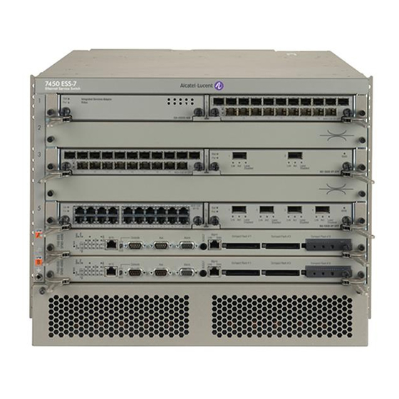
The AC and DC PEMs, fan and filter trays are accessible from the chassis rear. Figure 1 shows a front view of the 7450 ESS-7 chassis with AC PSMs installed in the lower front power bays. The mounting brackets for the 7450 ESS-7 chassis are factory installed to front mount the chassis in a standard 19-inch wide rack. - Page 17 Blank panel installed in empty IOM slot SF/CPM ESD plug receptacle AC PSMs (AC-to-DC power converters) IOM ejector lever Compact flash slot #3 locking mechanism Power supply module LEDs ESS7001 Figure 2: 7450 ESS-7 Chassis Front View (with Front Safety Cover) 7450 ESS-7 Page 17...
- Page 18 Chassis Features Figure 4 Figure 3 display the 7450 ESS-7 rear view with DC and AC PEMs installed in bays (slots) 1 and 2. Refer to Table 3 for key descriptions. SR70046 Figure 3: 7450 ESS-7 Chassis Rear View (DC version)
- Page 19 7450 ESS-7 Overview SR70047 Figure 4: 7450 ESS-7 Chassis Rear View (AC version) Table 4: Chassis Rear View Features Description Filter tray faceplate Fan tray faceplate Rack mounting brackets Captive screw PEM handle Power cord retainer AC power cord AC circuit breaker (ON/OFF)
-
Page 20: Sf/Cpms
MDAs on page 26 SF/CPM The SF/CPM controls the routing and switching functions for the entire 7450 ESS-7 system. The ESS-7 operates with at least one SF/CPM installed. The redundant SF/CPM operates in standby mode and takes over system operation if the primary fails. - Page 21 7450 ESS-7 Overview Table 5 displays the SF/CPM field and LED descriptions. Table 5: SF/CPM Field Descriptions Label/Part Description category Captive screws Secures the SF/CPM in place. Ejector lever Ejector levers are used to seat and disengage the connectors to and from the backplane.
- Page 22 • Only LED 1 and 2 illuminate for the 7450 ESS-7 model. • In the In the 7450 ESS-7 model, the fan status LEDs on the secondary SFM will light similarly to the primary SFM. A fault is indicated in one SFM if the primary fan status LED and the comparable secondary LED differ.
- Page 23 • The BITS port is provisioned with a RJ-45 jack and used for the network clock source. • In the In the 7450 ESS-7 model, the fan status LEDs on the secondary SFM will light similarly to the primary SFM. A fault is indicated in one SFM if the primary fan status LED and the comparable secondary LED differ.
- Page 24 Compact flash slot locking When engaged, the locking mechanism prevents the accidental jostling or mechanism removal of the flash card inserted in Compact Flash Slot #3. Page 24 7450 ESS-7...
- Page 25 EDUNDANT YSTEMS The 7450 ESS-7 switch is capable of a 1:1 Control Processor Module (CPM) redundancy scheme. Redundancy methods facilitate system synchronization between the active and standby CPMs so they maintain identical operational parameters to prevent inconsistencies in the event of a CPM failure.
-
Page 26: Ioms
(channelized and concatenated) and ATM. Each input/output module (IOM) features a single-slot baseboard carrying up to two hot-swappable MDAs. Alcatel-Lucent’s Ethernet MDAs for the 7450 ESS provide the critical high-speed interfaces. An MDA is a plug-in module allowing selection among fiber-optic, twisted pair, and coaxial cable. A maximum of 2 MDAs can be installed on each IOM. -
Page 27: Power Supplies And Redundancy
(PEM) can support the full system current requirements if you are operating the 7450 ESS-7 without power redundancy. The PSM is also referred to as an AC-to-DC power converter. For redundancy, two DC PEMs or the combination of two PSMs (for AC-to-DC power conversion) and two AC PEMs must be installed and powered on at all times. - Page 28 Chassis Features SR70022 Figure 6: 7450 ESS-7 DC Power Entry Module Page 28 7450 ESS-7...
- Page 29 One AC PSM and one AC PEM can support the full system current requirements if the 7450 ESS- 7 is operating without power redundancy. For redundancy, two AC PSMs and two AC PEMs must be installed and powered on at all times. SR70010A Figure 7: 7450 ESS-7 AC Power Supply Module (PSM) 7450 ESS-7 Page 29...
- Page 30 AC P OWER NTRY ODULES Two bays in the rear of the 7450 ESS-7 chassis are designated for swappable, load-sharing power entry modules (PEM) (Figure 8). One AC PEM and one AC PSM can support the full system current requirements if you are operating the 7450 ESS-7 without power redundancy. For redundancy, two AC PEMs and two AC PSMs must be installed and powered on at all times.
-
Page 31: Fan Trays
7450 ESS-7 Overview RAYS The 7450 ESS-7 system is cooled by either a dual-tray system that houses two fans on each tray (Figure 9) or a single high flow fan tray that houses four fans (Figure 10). Air is pulled through the system from a left-side filtered-intake vent, across the line cards and then exits through the two rear fan trays. - Page 32 Chassis Features SR70027 Figure 9: Fan Tray - Dual Fan Tray Example SR70049 Figure 10: Fan Tray - Single Fan Tray Example Page 32 7450 ESS-7...
-
Page 33: Air Filter
The fan tray must always be installed and fully operational while the 7450 ESS-7 is powered up. During routine maintenance and fan tray replacement, the system can operate safely for up to approximately 5 minutes at an ambient temperature of 95°F (35°C). -
Page 34: Component Operating Requirements
Chassis Features OMPONENT PERATING EQUIREMENTS Table 6 Table 7 display the 7450 ESS-7 hardware component operating requirements. Table 6: 7450 ESS-7 Hardware Components for DC Operational Requirements Component Minimum Maximum Field-Replaceable Backplane (factory installed) DC PEM 1 per module Power cables... - Page 35 7450 ESS-7 Overview 7450 ESS-7 S YSTEM NSTALLATION ROCESS To install the 7450 ESS-7 system, perform the installation procedures in the following order: Prepare the site. Step 1 Step 2 Unpack the chassis and components. Step 3 Mount the chassis.
-
Page 36: Ess-7 System Installation Process
7450 ESS-7 System Installation Process Page 36 7450 ESS-7... -
Page 37: Site Preparation
Site Preparation In This Chapter This chapter provides information about preparing your site to install a 7450 ESS-7 chassis. This chapter provides an overview of the following topics: • Warnings and Notes on page 38 • System Specifications on page 39 →... -
Page 38: Warnings And Notes
• Maintain adequate air flow to and from all equipment in the rack that might interfere with the normal flow of cooling air through the chassis. • The 7450 ESS-7 includes factory installed rack mounting brackets to install in a 19-inch equipment rack. -
Page 39: System Specifications
Acoustic noise level NEBS: ETSI 72.36 dBA (dual fan trays) 75.86 dBA (dual fan trays) 71.78 dBA (single high-flow fan tray) 76.75 dBA (single high-flow fan tray) Power consumption 2400W (min/max) Nominal power required per 240W slot (max) 7450 ESS-7 Page 39... -
Page 40: Power Module Specifications
Characteristics Using AC PEMs: Input 200-240VAC 15A ~ 11A 50/60 Hz Output -48V Note that each power supply is capable of providing in excess of 50A. Using DC PEMs: Input -40VDC — -72VDC 60A — 34A Page 40 7450 ESS-7... -
Page 41: Component Power Consumption
MDAs 10/100ETH-TX (60-port) 100BASE-FX (20-port) GigE + 1-port 10GBASE (10-port) 1GB-SFP-B (5-port) 1GB-SFP (10-port) 1GB-SFP-B (10-port) 1GB-SFP (20-port) 1GB-TX (20-port) 10GB-LW/LR (1-port) 10GB-EW/ER (1-port) 10GB-ZW/ZR (1-port) 10GB-XFP (1-port) 10GB-XFP (2-port) OC-3-SFP (16-port) OC-12-SFP (8-port) OC-12-SFP (16-port) 7450 ESS-7 Page 41... - Page 42 Table 13: MDA Power Consumption (Continued) Component Maximum Power Consumption (Watts) OC-48/STM-16 (2-port) GigE + 1-port 10GBASE (10-port) Versatile Service Module (VSM) (No ports) Table 14: Board Power Consumption Component/ Board Maximum Power Consumption (Watts) iom-20g-b iom-10g 200g SFM2 200g Page 42 7450 ESS-7...
-
Page 43: Component Specifications
H x 14.25 W x 7.5 fan tray dimensions " connector, add .5 . There are no handles on the high flow fan tray: " " " H x 14.25 W x 8.0 Weight: 13.3 lbs. (6.03 kg) 7450 ESS-7 Page 43... -
Page 44: The Equipment Rack
The equipment rack rail mounting holes must align with the mounting holes on the chassis mounting brackets. The mounting brackets are factory installed for a front mount in a 19-inch rack. Required tools: • #2 Phillips screwdriver • Flathead screwdriver • Anti-static bags, mats, and packaging • ESD wrist strap Page 44 7450 ESS-7... -
Page 45: Rack Clearance Requirements
CPM, IOMs, MDAs, and AC PSMs in the front and allow space to remove and install the fan and filter trays and DC or AC PEMs in the rear. 20” REAR REQUIRED FOR MAINTENANCE REAR 3” SIDE RECOMMENDED FOR AIR FLOW AND MAINTENANCE FRONT 20” FRONT REQUIRED FOR MAINTENANCE Figure 11: Chassis Clearance Requirements 7450 ESS-7 Page 45... -
Page 46: Safety Considerations
Safety Considerations Placement Warning: • Install the 7450 ESS-7 chassis in standard sized equipment racks. The 7450 ESS-7 is shipped with the 19-inch rack mounting brackets installed. • In clean, dry, ventilated, and temperature-controlled rooms. • Verify that the rack is properly bolted and braced and is properly grounded to a grounding electrode. -
Page 47: Cabling
• The PEM circuit breaker is not intended to be used as the chassis ON/OFF switch. Unplug the power cord from the power source and disconnect the cord from the receptacle on the power module to remove power. 7450 ESS-7 Page 47... -
Page 48: Fans
Safety Considerations Fans The 7450 ESS-7 cooling system must have at least 3-inches of unrestricted unobstructed front and rear air flow to function properly. The fan tray must be in place before the chassis is powered on. Blank panels and faceplates are required in all empty card and component slots to prevent excess dust accumulation and to help control airflow and electromagnetic interference. -
Page 49: Storage
To store unused components and extra field-replaceable parts, re-wrap the components in the original packaging and keep them in a dry, dust-free temperature controlled environment. Table 16: Storage Specifications Parameter Description Storage temperature From -40° to 158°F (-40° to 70°C) Non-condensing relative humidity Within 5 to 95 percent. 7450 ESS-7 Page 49... -
Page 50: Safety Standards/Compliance Agency Certifications
• CR-63-CORE • SBC-TP-76200 Environmental TS 300 019-1-1, Storage Tests, Class 1.2 ETS 300 019-1-2, Transportation Tests, Class 2.3 ETS 300 019-1-3, Operational Tests, Class 3.2 ETS 300 019-2-4 pr A1 Seismic ETS 300 753 Acoustic noise Page 50 7450 ESS-7... - Page 51 7450 ESS-7 NSTALLING THE HAPTER This chapter provides information about installing a 7450 ESS-7. This chapter provides information on the following topics: • Unpacking the Chassis on page 52 → Unpacking Precautions on page 52 • Rack Mounting the Chassis on page 54 •...
-
Page 52: Unpacking The Chassis
Do not discard the packaging container and materials used in shipping. The packing materials should be re-used if it is necessary to relocate the chassis. • Keep the 7450 ESS-7 wrapped in the anti-static packaging until you are ready to install the system. •... - Page 53 The chassis shipping weight is approximately 60 lbs. (27.22 kg). With two people, carefully remove the chassis from the carton’s base. Caution: There are no handles or hand grips on the 7450 ESS-7. Lift by the bottom of the chassis. Do not put your hands inside the chassis to lift. 7450 ESS-7...
-
Page 54: Rack Mounting The Chassis
• Only trained and qualified personnel should install or replace this equipment. Caution: • There are no handles or hand grips on the 7450 ESS-7. Lift the chassis from underneath. Do not lift the chassis by the internal frame. • When rack mounting the 7450 ESS-7 in an equipment rack, do not stack other units or any other equipment directly on top (where the bottom unit is supporting other devices). - Page 55 Installing the 7450 ESS-7 SR70004 Figure 13: Installing the 7450 ESS-7 Chassis Table 18: Rack Mounting the 7450 ESS-7 Chassis Description Equipment rack Rack mounting screws Rack mounting bracket 7450 ESS-7 Page 55...
- Page 56 (Optional) Slide the chassis on top of the shelf / bar. Step 4 Align the four mounting holes on each bracket to the rack rail. Insert a screw into each hole in the mounting bracket and tighten. Do not skip any holes. Page 56 7450 ESS-7...
-
Page 57: Preparing The Ground Wire
Danger: Only trained and qualified personnel should install or replace this equipment. When wiring any Alcatel-Lucent 7450 system, the ground connection must always be Notes: made first and disconnected last. -
Page 58: Making The Chassis Ground Connection
Using a wire-stripping tool, strip each the insulation from the wire to 1 5/16-inches. Step 1 Slide the open end of the ground lug (accessory box) over the exposed area of the prepared Step 2 wire. Using a crimping tool, crimp the ground lug to the wire. Step 3 Page 58 7450 ESS-7... - Page 59 Installing the 7450 ESS-7 AKING THE ROUND IRING ONNECTION The grounding receptacles are located in two places on the chassis for easier access depending on your rack configuration. Make the ground wire on either the right lower side of the chassis or the top left side.
- Page 60 Torque each bolt screw to 56 pound-inches. Do not overtighten. Step 4 Connect the opposite end of the grounding cable to the appropriate grounding point at your site to ensure adequate chassis ground according to local safety codes. Page 60 7450 ESS-7...
-
Page 61: In This Chapter
Installing Power Modules In This Chapter This chapter provides information about installing the DC power entry modules (PEMs) and AC PSMs and AC PEMs in the 7450 ESS-7 chassis. This chapter provides information on the following topics: • General Power Warnings and Notes on page 62 •... -
Page 62: General Power Warnings And Notes
• Electrostatic discharge (ESD) damage can occur if components are mishandled. Always wear an ESD-preventive wrist or ankle strap and always connect an ESD strap to the grounding plug on the front of the chassis. Page 62 7450 ESS-7... - Page 63 Installing Power Modules Notes: • The 7450 ESS-7 requires a minimum of one DC PEM or one AC PSM and one AC PEM to operate. Additional power units are recommended for redundancy. • For full redundancy, each PEM should be attached to an independent power source with a dedicated circuit breaker.
-
Page 64: Installing Dc Pems
• Confirm that the DC power source is OFF during installation. The power source should be a safety extra-low voltage (SELV) source. • The 7450 ESS-7 chassis with DC PEMs should be installed only in restricted access areas (such as dedicated equipment rooms and electrical closets) in accordance with Articles 110-26 and 110-27 of the most recent National Electrical Code ANSI/NFPA 70. - Page 65 • Overtightening the lugs can lead to PEM damage and subsequent electrical failure. • The 7450 ESS-7 requires a minimum of one DC PEM to operate, but two are recommended for redundancy. When two PEMs are installed, they share the electrical load as long as both PEMs are operational.
-
Page 66: Installing A Dc Pem
Figure 16 shows the proper installation of the right and left DC PEMs. SR70041 Figure 16: Installing a DC PEM Table 21: DC PEM Features Description Slot guide DC PEM Captive screws Terminal block safety cover Page 66 7450 ESS-7... - Page 67 Slide the unit into the slot until the connectors are seated with the receptacle in the rear of the slot. Step 6 Secure into place by tightening the captive screws. Step 7 Follow the steps to prepare and connect the power cord(s). See Preparing the Power Cable on page 7450 ESS-7 Page 67...
-
Page 68: Dc-Input Power Wiring
The length of the power cable depends on the location of the router and proximity to the power source. 0.250 .200 2 Holes 0.750" .625 All measurements in inches. SR12030 Figure 17: DC Terminal Block Lug SR10030 Figure 18: Preparing the DC Cable Page 68 7450 ESS-7... - Page 69 .625-inch (1.6 cm) spacing. Slide the open end of the lug over the exposed area of the prepared wire. Step 3 Using a crimping tool, crimp the lug to the wire. 7450 ESS-7 Page 69...
-
Page 70: Dc Input Terminal Block Wiring
DC-input terminal block safety cover and wiring views. SR70017A Figure 19: Wiring the DC-Input Power Terminal Block Table 23: DC-Input Terminal Block Descriptions Description DC terminal block studs Washer Washer Terminal block stud nuts Safety cover Safety cover screws DC power cords Page 70 7450 ESS-7... - Page 71 Place the washer and nut on the stud and tighten with a torque wrench to 27 pound-inches. Step 6 Do not overtighten. Step 7 Replace the safety cover and secure into place by tightening the captive screws (Figure 20). Figure 20: DC-Input Power Terminal Block Wiring with Safety Cover 7450 ESS-7 Page 71...
-
Page 72: Installing Ac Power Components
Notes: If you intend to use AC power entry modules in the 7450 ESS-7, observe the following guidelines: • AC power modules operate with a nominal utility system voltage of 200V to 240V, but will operate with input voltages ranging from 175 to 264 VAC. -
Page 73: Installing An Ac Psm
PSM installed in the front power slot 2 corresponds to the AC PEM installed in the rear power slot Table 24 describes the chassis and power module features depicted in Figure 21 Figure Chassis Top View SR70038A Figure 21: AC PEM and AC PSM Installation 7450 ESS-7 Page 73... - Page 74 Installing AC Power Components If you operate the 7450 ESS-7 chassis without redundant AC power, the AC PSM and AC PEM must be installed in either AC PSM 1 and AC PEM slot 1 or AC PSM 2 and AC PEM slot 2. There...
- Page 75 23). The front safety cover must be removed in order to install and replace the power converters. SR70005A Figure 23: Installing an AC PSM Table 25: AC-to-DC Converter Installation Features Description Safety cover AC PSM handle Captive screws Screw receptacle 7450 ESS-7 Page 75...
- Page 76 Firmly press the power converter all the way into the slot. Step 4 Tighten captive screws. Step 5 (Optional) Install a redundant AC PSM into the other slot. Replace the front safety cover and tighten captive screws. Step 6 Page 76 7450 ESS-7...
-
Page 77: Installing An Ac Pem
Installing Power Modules Installing an AC PEM SR70050 Figure 24: Installing an AC PEM Table 26: AC Power Entry Module Installation Features Description AC PEM Slot guide Captive screw PEM handle 7450 ESS-7 Page 77... - Page 78 Slide the unit into the slot and firmly press the unit all the way into the slot. Tighten the captive screws. (Optional) Install the redundant power module into the other rear power slot. Step 4 Step 5 Verify that the correlating AC PEM is properly installed in the appropriate slot. Page 78 7450 ESS-7...
-
Page 79: Connecting The Ac Power Cord
Plug the other end of the power cord into the AC power source receptacle. Step 4 Step 5 Turn the circuit breaker on each unit to the ON position ( | ). Step 6 Proceed to Installing the SF/CPM on page 7450 ESS-7 Page 79... - Page 80 Installing AC Power Components SR70019 Figure 26: AC PEM Wiring Table 28: AC PEM Installation Features Description AC power entry module Power entry module handle AC power cord Cord retainer Circuit breaker (ON/OFF) Captive screw Page 80 7450 ESS-7...
-
Page 81: Installing The Sf/Cpm
Using the Compact Flash Slot #3 Locking Mechanism on page 86 • Initial system Startup on page 87 → Troubleshooting on page 87 • Establishing Connections on page 90 → Console Connection on page 90 → Telnet Connection on page 92 7450 ESS-7 Page 81... -
Page 82: Installing Sf/Cpm Modules
• Always place chassis components on an anti-static surface. • Do not power up the 7450 ESS-7 chassis until all components are installed and verified. • Blank panels and faceplates are required in all empty card and component slots to prevent excess dust accumulation and to help control airflow and electromagnetic interference. -
Page 83: Installing The Sf/Cpm
Slot A or B. The next CPM installed in the same chassis then assumes the role as the standby CPM. If only one CPM is installed in the 7450 ESS-7 chassis, it becomes the active CPM regardless of the slot it is installed in. - Page 84 (Optional) Install the redundant SF/CPM in the other lower chassis slot. Step 6 Step 7 Establish a console connection. See Console Connection on page Page 84 7450 ESS-7...
- Page 85 (cf3). Configurations and executable images can be stored on flash cards or an FTP file location. • The flash card containing the bootstrap and boot option files must be installed in Compact Flash Slot #3 (cf3) on the SF/CPM. • You must have a console connection. See Console Connection on page 7450 ESS-7 Page 85...
-
Page 86: Initializing The System
Align the compact flash card with the slot guides. Insert the card until it is completely Step 3 seated in the slot. Do not force the card into the slot. Step 4 Lower the slot cover and tighten the locking screw. Page 86 7450 ESS-7... -
Page 87: Troubleshooting
When the image is successfully loaded, control is passed from the boot loader file to the image. The runtime image attempts to locate the configuration file as configured in the BOF. The configuration file include chassis, IOM, MDA, and port configurations, as well as system, routing, and service configurations. 7450 ESS-7 Page 87... -
Page 88: Initial System Startup
No disk in cf3 Error - file boot.ldr not found on any drive Please insert CF containing boot.ldr. Rebooting in 5 seconds. Rebooting... Alcatel-Lucent Build: X-0.0.x.x on Thu Jul 10 21:04:50 2003 by builder Starting CPU/Switch card Page 88 7450 ESS-7... - Page 89 — minor release number Y:A — Alpha release B — Beta release M — Maintenance release R — Released software z — Version number → cpm.tim — CPM image file → iom.tim — IOM image file 7450 ESS-7 Page 89...
-
Page 90: Establishing Connections
A standard serial cable with a female DB9 connector. For pinout information, refer to Appendix C: Pinout Assignments on page 153. Table 30: Console Configuration Parameter Values Parameter Value Baud Rate 115,200 Data Bits Parity None Stop Bits Flow Control None Page 90 7450 ESS-7... - Page 91 Step 3 Establish the connection by pressing the <Enter> key a few times on your terminal keyboard. At the prompt, enter the login and password. Step 4 The default login is admin The default password is admin 7450 ESS-7 Page 91...
-
Page 92: Telnet Connection
The 7450 ESS-7 must have a management IP address. The IP address is manually configured. Each 7450 ESS-7 switch is limited to a total of 7 Telnet or SSH sessions. For information about configuring switch parameters, refer to the 7450 ESS-7 OS System Guide. - Page 93 To establish a Telnet connection, run a Telnet program and issue the Telnet command, followed by the IP address: The following displays an example of a Telnet login: C:\>telnet 192.168.1.111 Login: admin Password: ######## ALA-7# 7450 ESS-7 Page 93...
- Page 94 Step 2 Press the ejector button on compact flash slot #1 or compact flash slot #2. The card will partially pop out of the slot. Remove the card and place it in an anti-static bag. Step 3 Page 94 7450 ESS-7...
-
Page 95: Installing Ioms And Mdas
Configuring Chassis Slot, IOM, and MDA Parameters on page 96 • Installing IOMs on page 99 • Installing MDAs on page 102 → Installing an MDA on an IOM on page 103 → Installing an MDA on a Chassis-Installed IOM on page 105 7450 ESS-7 Page 95... -
Page 96: Configuring Chassis Slot, Iom, And Mda Parameters
CLI commands and syntax examples to config>card provision the chassis slot and IOM: Command Example Step 1 card slot-number card 1 Step 2 card-type card-type card-type iom-20g Step 3 no shutdown no shutdown Page 96 7450 ESS-7... -
Page 97: Configuring Mda Parameters
The following example displays card slot, card type, MDA slot, and MDA type command usage: ALA-7>config# card 1 ALA-7>config>card# card-type iom-20g ALA-7>config>card# mda 1 ALA-7>config>card>mda# mda-type m60-10/100eth-tx ALA-7>config>card>mda# no shutdown ALA-7>config>card>mda# exit ALA-7>config>card# mda 2 ALA-7>config>card>mda# mda-type m10-1gb-sfp ALA-7>config>card>mda# no shutdown ALA-7>config>card>mda# exit 7450 ESS-7 Page 97... - Page 98 Configuring Chassis Slot, IOM, and MDA Parameters The following example displays the configuration: ALA-7>config# info . . . ---------------------------------------------- echo "Card Configuration " #------------------------------------------ card 1 card-type iom-20g mda 1 mda-type m60-10/100eth-tx exit mda 2 mda-type m10-1gb-sfp exit exit ---------------------------------------------- ALA-7>config# Page 98 7450 ESS-7...
-
Page 99: Installing Ioms
• Always place router components on an anti-static surface. • Do not power up the 7450 ESS-7 router until all components are installed and verified. • Blank panels and faceplates are required in all empty card and component slots to prevent excess dust accumulation and to help control airflow and electromagnetic interference. -
Page 100: Installing Ioms
Note: The ejector levers must be positioned inward during the card installation. SR70007 Figure 32: Installing an IOM Table 31: Installing IOM Features Description Slot guide IOM positioned between the slot guides IOM captive screw Ejector lever Page 100 7450 ESS-7... - Page 101 Pull the IOM out halfway, verify the card is moving properly in the slot guides and then reinsert it. Shift the levers to the locked position. Secure into place by tightening the captive screws. Step 5 7450 ESS-7 Page 101...
-
Page 102: Installing Mdas
Avoid exposure and do not stare into open apertures. • Always place components on an anti-static surface. • Do not power up a 7450 ESS-7 until all components are installed and verified. • Use only approved small form factor pluggable GBIC fiber optic devices in MDA ports. -
Page 103: Installing An Mda On An Iom
MDAs can be installed on an IOM before installing the IOM into the chassis. SR40021A Figure 33: Installing an MDA on an IOM Table 32: MDA Installation Features Description Captive screw MDA handle Connectors Threaded receptacle Slot guides 7450 ESS-7 Page 103... - Page 104 IOM receptacle. The faceplate of the MDA should be flush with the IOM faceplate. Step 4 Tighten the captive screws to secure the MDA. Do not over-tighten. The maximum recommended torque is 10 lbf.in. Step 5 Check the Power LED. Attach cables to the MDA ports. Step 6 Page 104 7450 ESS-7...
-
Page 105: Installing An Mda On A Chassis-Installed Iom
Installing an MDA on a Chassis-Installed IOM ESS7005 Figure 34: Installing an MDA in an IOM in the Chassis Table 33: MDA Features Description Example of an installed MDA Captive screw MDA slot guides Threaded receptacle 7450 ESS-7 Page 105... - Page 106 Tighten the captive screws to secure the MDA. Do not over-tighten. The maximum recommended torque is 10 lbf.in. Check the Power LED on the MDA faceplate. Step 5 Step 6 Attach cables to the MDA ports. Page 106 7450 ESS-7...
-
Page 107: Mda Leds
• Amber: SFP/optics installed but no link present. • Unlit: Disabled, shut down. • Green (blinking): RX/TX: Port is active, transmitting and receiving data. • Amber (fast blinking): Indicates an error condition. • Unlit: Disabled, shut down. MDA model number. 7450 ESS-7 Page 107... - Page 108 Installing MDAs Page 108 7450 ESS-7...
-
Page 109: Ac Power Supply Module Leds
A: LED PPENDIX S AND PTICS HAPTER This section describes the 7450 ESS-7 PSM and SF/CPM LEDs. MDA LEDs are described in the MDA documentation. The following LED descriptions are included: • AC Power Supply Module LEDs on page 110 •... - Page 110 LEDs and Optics AC P OWER UPPLY ODULE SR70026 Figure 36: AC Power Supply Module Table 35: AC PSM LED Descriptions Symbol Label Color AC_ON Green Power_Good (48Vdc ON) Green OK_to_remove Amber Fault Page 110 7450 ESS-7...
-
Page 111: Sf/Cpm Leds
Master/Slave SF/CPM designation: • Green: Indicates that the SF/CPM is designated as the primary SF/CPM in a redundant system. • Green (blinking): Indicates that the SF/CPM is operating as the secondary SF/CPM in a redundant configuration. 7450 ESS-7 Page 111... - Page 112 • Only LEDs 1 and 2 illuminate for the 7450 ESS-7 model. • In the 7450 ESS-7 model, the power supply LEDs on the secondary SFM will light similarly to the primary SFM. A fault is indicated in one SFM if the primary power supply LED and the comparable LED differ.
- Page 113 • In the 7450 ESS-7 model, only LED 1 and 2 illuminate. • In the In the 7450 ESS-7 model, the fan status LEDs on the secondary SFM will light similarly to the primary SFM. A fault is indicated in one SFM if the primary fan status LED and the comparable secondary LED differ.
- Page 114 Compact Flash #2 (Slot) • Default filename: cf2: • See the Compact Flash LED description for the status of a compact flash slot. • To eject a flash card, gently depress the ejector button until the flash card releases. Page 114 7450 ESS-7...
- Page 115 Compact flash slot locking When engaged, the locking mechanism prevents the accidental jostling or mechanism removal of the flash card inserted in Compact Flash Slot #3. 7450 ESS-7 Page 115...
- Page 116 LEDs and Optics Page 116 7450 ESS-7...
- Page 117 B: F PPENDIX IELD EPLACEABLE NITS HAPTER This chapter provides information about field replaceable units (FRUs) in the 7450 ESS-7 chassis. Topics in this chapter include: • Power Modules on page 118 • SF/CPMs on page 129 • IOMs on page 133 •...
-
Page 118: Power Modules
• You must use power cables which meet local electrical code requirements. Caution: • There are no handles or hand grips on the 7450 ESS-7. Lift the chassis from underneath. Do not lift the by the internal chassis frame. Warning: •... - Page 119 Field Replaceable Units Notes: • The 7450 ESS-7 requires a minimum of one DC PEM or one AC PSM and one AC PEM to operate. Additional modules are recommended for redundancy. • For full redundancy, each PEM should be attached to an independent power source with a dedicated circuit breaker.
-
Page 120: Dc Power
DC PEM EMOVING A If you are operating your 7450 ESS-7 with redundant DC PEMs, you can remove and replace a single PEM without affecting your system’s operation. If you are operating your 7450 ESS-7 with only one DC PEM, the system will shut down when power to the PEM is removed. - Page 121 Loosen the captive screws and slide the DC PEM out of the slot (Figure 38). Step 6 If you do not replace the PEM immediately, install a blank panel to prevent excess dust Step 7 accumulation and to help control airflow and electromagnetic interference. 7450 ESS-7 Page 121...
-
Page 122: Replacing A Dc Pem
Field Replaceable Units DC PEM EPLACING A SR70041 Figure 39: Replacing a DC PEM Table 38: DC PEM Features Description Slot guide DC PEM handle Captive screw (2 per PEM) Terminal block safety cover Page 122 7450 ESS-7... - Page 123 Panduit LCC6-10A-L. Tighten with a torque wrench to 27 pound- inches. Do not overtighten. Step 6 Replace the safety cover (Figure 40). Step 7 Flip the circuit breaker (ON/OFF) on the PEM to the ON position when ready. Figure 40: Replace the Safety Cover 7450 ESS-7 Page 123...
-
Page 124: Ac Power
AC PSM EMOVING AN If you are operating your 7450 ESS-7 system with redundant AC PSMs and AC PEMs, you can install, remove, or replace a power module without affecting system operation. To assure safety, flip the circuit breaker (ON/OFF) on the PEM to the OFF ( O ) position while replacing a AC PSM. -
Page 125: Replacing An Ac Psm
Align captive screws with the screw receptacles in the slot. Firmly press the power converter all the way into the slot.Tighten the captive screws. Step 5 (Optional) Install a redundant AC PSM into the other slot. Replace the front safety cover and tighten captive screws. Step 6 7450 ESS-7 Page 125... - Page 126 Step 5 If you are installing a replacement PEM, proceed to the next section, Replacing an AC PEM on page 127. If you are not installing a replacement PEM, replace the empty slot with a blank faceplate. Page 126 7450 ESS-7...
-
Page 127: Replacing An Ac Pem
AC PSM populates. For example, if the PSM is installed in front power slot 1, install the AC PEM in rear power slot 1. Slide the PEM into the slot and firmly press the unit all the way into the slot. Tighten the captive screws. 7450 ESS-7 Page 127... - Page 128 Step 8 Plug the other end of the power cord into the AC power source receptacle. Step 9 Turn the circuit breaker (ON/OFF) on the PEM to the ON position ( | ). Page 128 7450 ESS-7...
-
Page 129: Sf/Cpms
SF/CPM module, replace the empty slot with a blank panel and power off the system until the SF/CPM module is replaced 7450 ESS-7: • Accommodates two SF/CPMs, one active and one standby. One SF/CPM is required for operation. -
Page 130: Removing An Sf/Cpm
Step 4 Simultaneously, rotate the ejector levers inward to unlock the panel. Pull the card out of the slot. Place on an anti-static surface or in an anti-static bag. Step 5 SR70029 Figure 45: Removing an SF/CPM Page 130 7450 ESS-7... - Page 131 The ejector levers must remain in the locked position while the card is installed in the chassis. SR70008 Figure 46: Installing the SF/CPM Module Table 40: Installing SF/CPM Features Description Slot guide SF/CPM positioned in the slot guide SF/CPM captive screw (2 per SF/CPM) Ejector lever 7450 ESS-7 Page 131...
- Page 132 Pull the card out halfway and then reinsert it. Shift the levers to the locked position. Secure the card in place by tightening the captive screws. The ejector levers must remain Step 5 in the locked position while the card is installed in the chassis. Page 132 7450 ESS-7...
-
Page 133: Ioms
• When replacing an IOM, ports, MDAs, and card parameters must be shut down. • All 7450 ESS-7 systems require at least one IOM. • When you remove an IOM, always use the ejector levers to make sure that the connector pins disconnect from the backplane. - Page 134 Remove the MDA(s) and card from the configuration: Step 13 card# no mda slot-number no mda 1 Step 14 card# no mda slot-number no mda 2 Step 15 config# no card slot-number no card 1 Page 134 7450 ESS-7...
- Page 135 Step 7 mda slot-number mda 2 Step 8 mda mda-type mda-type m60-10/100eth-tx Step 9 no shutdown no shutdown Configure port: Step 10 port port-id port 1/1/1 Step 11 no shutdown no shutdown Continue port configurations as required. 7450 ESS-7 Page 135...
-
Page 136: Removing An Iom
If you are not replacing the IOM, install a blank panel in the empty slot, use a flathead Step 3 screwdriver to tighten the 2 captive screws. If you are replacing the IOM, proceed to the next section, Replacing an IOM. Page 136 7450 ESS-7... - Page 137 A blank panel must be installed in all empty chassis slots. To install a blank panel: Step 1 Align the blank and insert the blank into the chassis slot. Use a flathead screwdriver to tighten the 2 captive screws that fasten the blank panel to Step 2 the chassis. 7450 ESS-7 Page 137...
- Page 138 Field Replaceable Units EPLACING AN SR70007 Figure 48: Installing an IOM Table 41: Installing IOM Features Description Slot guide IOM positioned between the slot guides IOM captive screw Ejector lever Page 138 7450 ESS-7...
- Page 139 Pull the card out halfway, verify the card is moving properly in its slot guides and then reinsert it. Shift the levers to the locked position. Secure into place by tightening the captive screws. Step 5 7450 ESS-7 Page 139...
-
Page 140: Mdas
Avoid exposure and do not stare into open apertures. • Always place components on an anti-static surface. • Do not power up a 7450 ESS-7 chassis until all components are installed and verified. • Use only approved small form factor pluggable fiber optic devices in MDA ports. - Page 141 If you replace an MDA with a different type, you must change the configuration to reflect the new MDA type prior to the installation. Each active port must be shut down in order to shut down and remove an MDA configuration. Refer to the Alcatel-Lucent OS System Guide for details on configuring cards, MDAs, and ports.
- Page 142 Slide the MDA out of the slot. Step 3 Step 4 Place the MDA on an anti-static surface. You must either immediately install another MDA into the slot or replace the MDA slot Step 5 with blank cover. Page 142 7450 ESS-7...
- Page 143 Field Replaceable Units EPLACING AN SR70006 Figure 49: Installing an MDA Table 42: MDA Installation Features Description Example of an installed MDA Captive screws (2 per MDA) MDA slot guides Threaded receptacle 7450 ESS-7 Page 143...
- Page 144 IOM receptacle. Tighten the captive screws to secure the MDA. Do not over-tighten. The maximum Step 4 recommended torque is 10 lbf.in. Check the Power LED. Step 5 Step 6 Attach cables to the MDA ports. Page 144 7450 ESS-7...
-
Page 145: Fan Trays
• Verify that the fan blades have stopped rotating before removing the fan tray. Notes: • Fan trays are hot-swappable. The 7450 ESS-7 chassis operates safely while you replace a fan tray for up to approximately 5 minutes at an ambient temperature of 95° F (35° C). If a longer maintenance time is required, power off the system to prevent over temperature conditions. -
Page 146: Removing A Fan Tray
Field Replaceable Units EMOVING A SR70034 Figure 50: Removing a Fan Tray - Dual Fan Tray Example SR70045 Figure 51: Removing a Fan Tray - Single Fan Tray Example Page 146 7450 ESS-7... - Page 147 (about 20 seconds) before removing the fan tray. Step 4 When the fans stop spinning, remove the fan tray completely out of the slot. Step 5 Proceed to Replacing a Fan Tray on page 148. 7450 ESS-7 Page 147...
-
Page 148: Replacing A Fan Tray
Field Replaceable Units EPLACING A SR70011A Figure 52: Replacing a Fan Tray - Dual Fan Tray Example SR70040A Figure 53: Replacing a Fan Tray - Single Fan Tray Example Page 148 7450 ESS-7... - Page 149 Step 3 Make sure the connectors engage. Secure the fan tray faceplate into place by tightening the captive screws. Step 4 Verify the fan status LED on the SF/CPM. Step 5 7450 ESS-7 Page 149...
-
Page 150: Air Filter Tray
• The air filter is accessible from the rear of the chassis. Use a flathead screwdriver to loosen the captive screws. • The air filter should be inspected and cleaned at least monthly and replaced every 12 months. EMOVING THE ILTER Figure 54: Removing the Air Filter Page 150 7450 ESS-7... - Page 151 NOTE: Velcro tabs connect the filter tray to the filter tray faceplate. When you remove the filter faceplate, make sure the filter tray is attached. They should be removed as one unit. Detach the filter tray. Step 3 7450 ESS-7 Page 151...
- Page 152 Insert the replacement filter tray into the filter tray slot until the filter is fully inserted. Insert the air filter faceplate to cover the slot. Step 2 Step 3 Use a flathead screwdriver to tighten the captive screws. Page 152 7450 ESS-7...
-
Page 153: Sf/Cpm Port Types
Table 50, Auxiliary Port - DTE Mode Only - DB9 Male, on page 156 → Table 51, Alarm Port - DB9 Female, on page 157 → Table 52, 10/100 Management Ethernet Port - RJ45 Female, on page 157 7450 ESS-7 Page 153... - Page 154 The Management port is a 10/100 Ethernet port which is a channel to download images and manage the system. This port is provisioned with an RJ-45 jack on the front panel. You must provide a CAT5 Ethernet cable to connect to the port. Page 154 7450 ESS-7...
- Page 155 Signal Direction Description Input Data carrier detect Input Receive data Output Transmit data Output Data terminal ready Signal ground Signal ground Input Data set ready Output Request to send Input Clear to send Input Ring indicator 7450 ESS-7 Page 155...
- Page 156 Direction Description Not connected Input Receive data Output Transmit data DTR/DSR Output Data terminal ready/Data set ready Signal ground DSR/DTR Input Data set ready/Data terminal ready Output Request to send Input Clear to send Not connected Page 156 7450 ESS-7...
- Page 157 Table 52: 10/100 Management Ethernet Port - RJ45 Female Signal Direction Description Output Differential transmit data - positive Output Differential transmit data - negative Input Differential receive data - positive Not connected Not connected Input Differential receive data - negative Not connected Not connected 7450 ESS-7 Page 157...
- Page 158 Pinout Assignments Page 158 7450 ESS-7...
-
Page 159: Index
IOMs Console removing Telnet replacing removing replacing power overview attaching power cable electrical characteristics grounding ground connection ground connection ground wire 57, 68 7450 ESS-7 Page 159... - Page 160 22, 113 fans 22, 113 power supply 22, 112 MDAs changing configuration configuring installing pin assignments alarm port auxiliary port BITS port console port (DCE) console port (DTE) management port safety considerations fans filters Page 160 7450 ESS-7...
Need help?
Do you have a question about the 7450 ESS-7 and is the answer not in the manual?
Questions and answers