FS Fiberstore S8050-20Q4C Installation Manual
Fiberstore s8050 series
Hide thumbs
Also See for Fiberstore S8050-20Q4C:
- Configuration manual (7 pages) ,
- Quick start manual (46 pages)
Table of Contents
Advertisement
Advertisement
Table of Contents

Subscribe to Our Youtube Channel
Related Manuals for FS Fiberstore S8050-20Q4C


Summary of Contents for FS Fiberstore S8050-20Q4C
- Page 1 Fiberstore S8050 Series Switch Installation Guide...
- Page 3 Chapter 1 Product Introduction …………………………………………………..…………………………………………………..…... 1.1 Product Model …………………………..…………………………………………………..………..……….……….……… 1.2 Front Panel (S8050-20Q4C) ………………………………………………..……………………………………………… 1.3 Rear Panel (S8050-20Q4C) …………………………………………………..…………………………………………..1.4 FS S8050 Series Switch LED Introduction ………………………………………..………………………………... 1.4.1 System LED Indicator ……………………………………………………..……………………………………..…….. 1.4.2 FAN LED Indicator ……………………………………………………..………………………………………………….. 1.4.3 Power Supply LED Indicator ……………………………………………………..……………………………………...
- Page 4 INSTALLATION INSTRUCTIONS © FS.COM 2016 FS016 List of Tables Table 1-1 FS S8050 Series Switch Model .. ……………………………………………………..…………………………………..Table 2-1 Temperature/Humidity Requirements ………………………………………………..……………………………….….. Table 2-2 Dust Content Requirements in Switch Room ……………………..…………………………………………………... Table 2-3 Harmful Gas Threshold in the Equipment Room …………………………………..………………………….……...
-
Page 5: Chapter 1 Product Introduction
FS016 Chapter 1 Product Introduction The Fiberstore FS S8050 Series Routing Switch is a high performance Ethernet switch to meet next generation Metro, Data Center and Enterprise network requirements. FS S8050 supports L2/L3/Data Center/Metro features. The FS S8050 comes with complete system software with comprehensive protocols and applications to facilitate rapid service deployment and management for both traditional L2/L3 networks and Data Center networks. -
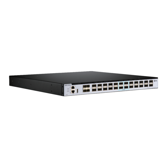
Page 6: Front Panel (S8050-20Q4C)
Figure 1-3 Rear Panel Sketch Map of S8050-20Q4C 1: Grounding Screw 2: AC or DC FRU Power Supply Module (PS1) 3: AC or DC FRU Power Supply Module (PS2) 4: Cooling Fans For Technical Support: www.fs.com/service.html Page 2 of 18... -
Page 7: Fs S8050 Series Switch Led Introduction
INSTALLATION INSTRUCTIONS © FS.COM 2016 FS016 1.4 FS S8050 Series Switch LED Introduction 1.4.1 System LED Indicator Indicator Status Description System is abnormality. Green Blinking Quickly (2Hz) The system is power on but CPU is not running. Blinking Slowly (0.5Hz) The system is normal running. -
Page 8: Ethernet Management Interface Led Indicator
40G packets are receiving or transmitting. (S8050-20Q4C) Port not link. 1.4.6 100G QSFP28 Indicator Indicator Status Description 100G port link. 11-14(S8050-20Q4C) Green Blinking 100G packets are receiving or transmitting. Port not link. For Technical Support: www.fs.com/service.html Page 4 of 18... -
Page 9: Chapter 2 Switch Installation
• 2.1.2 Installation Site To ensure a normal work environment, FS S8050 series switch should have the following requirements for workplace. Ensure that there are some spaces at the inlet and outlet of switch for heat dispersion of switch chassis. -
Page 10: Table 2-2 Dust Content Requirements In Switch Room
−FS S8050 series switch is Class 1 laser device. −Do not stare at the optical interfaces directly when the optional optical interfaces of FS S8050 series switch are in operating mode, since light beam emitting from fiber has high energy which may be harmful to retina. -
Page 11: Installation Tools
• The installation tools are not provided with FS S8050 Series Switch. 2.2 Installation FS S8050 series switch can be installed in the following 2 ways: Install the switch into a rack with Front Mounting Brackets (19” standard rack) •... -
Page 12: Install The Switch Into A Rack With Front Mounting Brackets
FS016 2.2.2 Install the Switch into a Rack with Front Mounting Brackets Installation Process (FS S8050) Step 1 Wear ESD-preventive wrist strap, and check the grounding and stability of rack. Step 2 Fix the tray to a proper position of rack horizontally. -
Page 13: Install The Switch On A Workbench
2.2.4 Installation and Removal of Power Module Installation Process The power module for FS S8050 series switch is pluggable. Installation process of power module is as follows: Wear ESD-preventive wrist strap, and confirm that the anti-static wrist strap is well earthed. -
Page 14: Figure 2-6 Removing Sketch Map Of Ac Power Module
© FS.COM 2016 FS016 Removal Process The power modules for FS S8050 series switch is pluggable. Removal process of power module is as follows: Wearing anti-static wrist strap, and confirm that the anti-static wrist strap is well earthed. • Disconnect all power connectors of the switch. -
Page 15: Chapter 3 Interface Module And Cable Connection Description
Chapter 3 Interface Module and Cable Connection Description 3.1 Interface Module Description 3.1.1 Ethernet Port FS S8050 series switch is integrated with out-of-band Ethernet ports whose interfaces are 100Base-TX or 10Base-T. It is recommended to use the net line included. 3.1.2 Console Port... -
Page 16: Chapter 4 Initial Power-On And Start-Up Of Switch
Click “Start → Program → Attachment → Communication → Super Terminal" to enter the super terminal window and establish a new connection, then a connection description interface will pop up as the following figure show. Figure 4-2 New Connection For Technical Support: www.fs.com/service.html Page 12 of 18... -
Page 17: Figure 4-3 Connection Port Setting
Click “OK” after setting the serial port parameters and the system enters the HyperTerminal window. Figure 4-4 HyperTerminal Window For Technical Support: www.fs.com/service.html Page 13 of 18... -
Page 18: Setting Terminal Parameter (Securecrt From Vandyke Software)
Click "Quick Connect" button to enter the SecureCRT quick connection window. Figure 4-6 Create a New Quick Connection 2. Choose the “Serial” as the Protocol. Figure 4-7 Serial Parameters Setting Interface (Protocol) For Technical Support: www.fs.com/service.html Page 14 of 18... -
Page 19: Switch Power-On
Enter after self-check, then command line DOS prompts (such as (Switch)) will appear. Type a command, configure Ethernet switches or view the running state of Ethernet switches. Enter "?" whenever you need a help. See the subsequent chapters of this manual for specific configuration commands. For Technical Support: www.fs.com/service.html Page 15 of 18... -
Page 20: Chapter 5 Switch Software Loading
Run TFTP Server program on PC as a server, and set the directory where loading files are located; uBoot file supposed to be upgraded is u_boot_v1.0.bin. Run the command upgrade_uboot u_boot_v1.0.bin to upgrade uBoot; here the filename is u_boot_v1.0.bin. Run the command reset to complete the upgrade of uBoot. For Technical Support: www.fs.com/service.html Page 16 of 18... -
Page 21: Chapter 6 Upgrade Of Operating System
INSTALLATION INSTRUCTIONS © FS.COM 2016 FS016 Chapter 6 Upgrade of Operating System FS S8050 Series Ethernet Switch can support new features and enhance system performance without replacing hardware by upgrading the operating system. Ethernet Management Port Ethernet Cable EJ45 Ethernet Port... -
Page 22: Chapter 7 Maintenance And Troubleshooting
If the configuration terminal displays hashes, it is probable that the parameter setting of terminal (such as super terminal) is incorrect. Please confirm the parameter setting of terminal (such as super terminal): baud rate: 115200, data bit: 8, parity: no, stop bit: 1, flow control: NA, selecting terminal emulation: VT100. For Technical Support: www.fs.com/service.html Page 18 of 18... - Page 23 FS016 V1.0 December 2016...
Need help?
Do you have a question about the Fiberstore S8050-20Q4C and is the answer not in the manual?
Questions and answers