Table of Contents
Advertisement
FlowCon SM 50-150mm
INSTALLATION AND OPERATION INSTRUCTION
Install the FlowCon SM valve either in the
supply or return pipe work for the unit. It is
recommended that a strainer be installed
prior to the valve body to prevent damage or
blockage due to debris. INSTALL THE VALVE
HOUSING WITH THE FLOW DIRECTIONAL
ARROW POINTING IN THE CORRECT
DIRECTION.
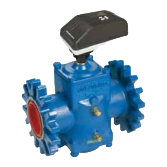
The valve body is available for double flange
connections, i.e figure 1.
O-rings are supplied with the valve body and
are used to seal the connections. Pls. make
sure these are in place in the o-ring grooves
in the inlet and outlet of the valve body, when
installing the housing.
FlowCon SM 50-150mm, 2"-6"
Denmark
DYNAMIC SELF BALANCING
It is recommended to grease the o-rings with
a silicone grease before installation.
IMPORTANT: Never use mineral oil or petrol
based grease or oil on the o-rings.
Valve bodies are as standard supplied with
pressure/temperature fittings (p/t plugs).
Before finger mounting the p/t plugs in the
body tappings, please seal the threads of the
p/t plugs (DO NOT OVER TIGHTEN).
Fitting and orientation
of the actuator
Pls. install the valve so that the actuator
is located upwards and not lower than the
horizontal line to prevent condensation into
the electronics (pls. see figure 2 next page).
Dubai
USA
- 1 -
CONTROL VALVE
Singapore
www.flowcon.com
1A95105 - 08/2016
FlowCon International assumes no responsibility
for mistakes, if any, in any printed material.
Figure 1
Advertisement
Table of Contents

Related Manuals for FlowCon SM.3.0


Summary of Contents for FlowCon SM.3.0
- Page 1 CONTROL VALVE INSTALLATION AND OPERATION INSTRUCTION FlowCon SM 50-150mm, 2”-6” Install the FlowCon SM valve either in the It is recommended to grease the o-rings with supply or return pipe work for the unit. It is a silicone grease before installation.
- Page 2 4 and the second 2.2Kohm resistor between mA, Pulse Width Modulation and Digital Tri- pins 1 and 3 (see figures 8 and 9). Denmark Dubai Singapore www.flowcon.com 1A95105 - 08/2016 FlowCon International assumes no responsibility - 2 - for mistakes, if any, in any printed material.
- Page 3 Figure 7 Figure 8 MODULATION 2-10VDC feedback PWM input and 4-20mA feedback DIGITAL TRI-STATE Figure 9 4-20mA feedback Denmark Dubai Singapore www.flowcon.com 1A95105 - 08/2016 FlowCon International assumes no responsibility - 3 - for mistakes, if any, in any printed material.
- Page 4 For Normally Open set Release the reset button. programming switch #1 to ON. The indication LED should remain illuminated. Denmark Dubai Singapore www.flowcon.com 1A95105 - 08/2016 FlowCon International assumes no responsibility - 4 - for mistakes, if any, in any printed material.
- Page 5 POWER. Failure to disconnect power may Press and release the reset cause damage to the actuator gears. Fit the button to memorize this value. manual over-ride key (FlowCon No. ACC0001) The LED should blink once as onto the valve spindle. Press the clutch. Rotate confirmation.
- Page 6 OFF OFF Accuracy: Greatest of either ±5% of controlled flow rate or ±2% of maximum flow rate. Denmark Dubai Singapore www.flowcon.com 1A95105 - 08/2016 FlowCon International assumes no responsibility - 6 - for mistakes, if any, in any printed material.
- Page 7 OFF OFF Accuracy: Greatest of either ±5% of controlled flow rate or ±2% of maximum flow rate. Denmark Dubai Singapore www.flowcon.com 1A95105 - 08/2016 FlowCon International assumes no responsibility - 7 - for mistakes, if any, in any printed material.
- Page 8 OFF OFF Accuracy: Greatest of either ±5% of controlled flow rate or ±2% of maximum flow rate. Denmark Dubai Singapore www.flowcon.com 1A95105 - 08/2016 FlowCon International assumes no responsibility - 8 - for mistakes, if any, in any printed material.
Need help?
Do you have a question about the SM.3.0 and is the answer not in the manual?
Questions and answers