Suspa MOVOTEC Manual
Dual-drive “bolt-on” lift system
Hide thumbs
Also See for MOVOTEC:
- Manual (30 pages) ,
- Manual (33 pages) ,
- Assembly instructions manual (19 pages)
Table of Contents
Advertisement
®
MOVOTEC
Dual-Drive "Bolt-On"
Lift System Manual
by
Copyright © 2013 by
®
Suspa
Incorporated
All rights reserved. No part of this manual may be reproduced or transmitted
in any form or by any means, electronic or mechanical, including photocopying,
recording, or by any information storage and retrieval system
®
without permission in writing from Suspa
Incorporated.
Advertisement
Table of Contents

Related Manuals for Suspa MOVOTEC


Summary of Contents for Suspa MOVOTEC
- Page 1 All rights reserved. No part of this manual may be reproduced or transmitted in any form or by any means, electronic or mechanical, including photocopying, recording, or by any information storage and retrieval system ® without permission in writing from Suspa Incorporated.
- Page 2 1.0 Table of Contents 2.0 Introduction ......................... 2 3.0 Safety Instructions ...................... 3 4.0 How it Works....................... 6 4.1 Extension Cycle: ......................6 4.2 Retraction Cycle: ....................... 7 5.0 Unpacking Instructions ....................7 6.0 Lift System Specifications ..................9 6.1 Lift Cylinder Specifications ..................10 6.2 Motorized Pump Specifications................
-
Page 3: Introduction
Movotec lift systems are assembled and subjected to a full function quality test before they leave our manufacturing facility. Suspa guarantees products are free from material and manufacturing defects, but cannot support the warranty for our products if they are altered, misused, misapplied, or abused in any way. -
Page 4: Safety Instructions
VERIFY SYSTEM SELECTION. Before the installing or operating the system, ® please review the application to confirm that the correct Movotec Lift System has been selected. Pay particular attention to the load capacity and adjustment range ratings listed on the orange pump warning label. - Page 5 OBSERVE DUTY CYCLE. The term duty cycle refers to the amount of time that a ® motor or system is in motion versus the amount of time that it is resting. The Movotec Dual-Drive “Bolt-On” Lift System is not designed to operate continuously without rest.
- Page 6 MAINTENANCE SAFEGUARDS. Prior to performing any maintenance or service on the device, remove the load from all lift cylinders and unplug the motor controller from power source. The workstation or structure that the lift system is attached to should be stabilized to prevent personal injury or property damage during maintenance or service procedures.
-
Page 7: How It Works
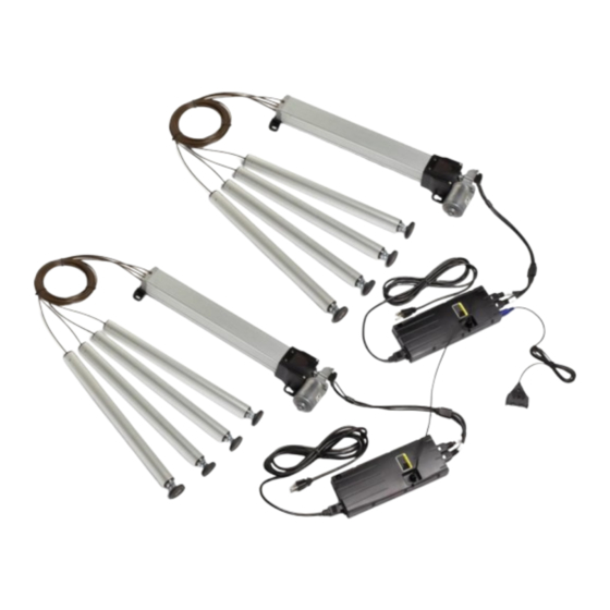
4.0 How it Works ® Dual-Drive “Bolt-On” Lift Systems are comprised of three major component Movotec subsystems; the motor drive, the pumps, and the lift cylinders. This section will explain how each subsystem works together to make the lift system extend and retract. -
Page 8: Retraction Cycle
The gear motors automatically shut off once the programmed pump upper limit is reached. ® 4.2 Retraction Cycle: (Refer to Movotec Dual-Drive Schematic on page 7) When the motor switch “DN” arrow button is depressed, the 24VDC gear motor shafts begin to rotate in a (CW) clockwise direction. - Page 9 (J) Motor Cable (connected to motor) (K) Controller Linking Cable If the lift system is damaged or any component is missing, please contact ® Suspa Incorporated to resolve the issue. Dispose of the all packaging materials in an ecologically sound manner. 01/11/13...
-
Page 10: Lift System Specifications
6.0 Lift System Specifications The “A”, “B”, and “Z” dimensions shown in the table and drawings below vary depending on the system lift capacity and the adjustment range of the selected system. US System Part Numbers Motorized CB "Bolt-On" Cylinder Lift System Adjustment System Lift... -
Page 11: Lift Cylinder Specifications
6.2 Motorized Pump Specifications (Refer to Chart on Page 11 for “Z” dimension) ® The Movotec gear motor used with the motorized pump shown below is rated for 24 volts DC. The no-load speed of the gear motor is 160 rpm. The no-load current is 3A. -
Page 12: Motor Controller Specifications
6.3 Motor Controller Specifications Motor Controller Parameter Specification 120V / 50-60Hz (US) Supply Voltage / Frequency 230V / 50-60HZ (Europe) <0.7W Standby Power Consumption Switch Operating Voltage / Current 5VDC / 150mA Hall Sensor Operating Voltage / Current 5VDC / 150mA 32º... - Page 13 6.4 Surface Mount Switch Specifications The operating voltage and current of the surface mount switch when attached to the motor controller is 5VDC and 150mA, respectively. 01/11/13 670- 00021A...
-
Page 14: System Component Placement
In addition, the motor controller should be placed so that it is ® in relatively close proximity to the gear motors. If this is not possible, Suspa Incorporated offers motor extension cables to make up the difference. These cables can be purchased on our website at http://shop.suspa.com. -
Page 15: Motorized Pump Installation
These cylinder mounting brackets can be purchased on our website at http://shop.suspa.com. 7.1.5 Tubing and Cable Placement – Hydraulic tubing and power cables must be kept away from sharp edges and moving parts. Contact with moisture and heat must also be avoided. -
Page 16: Motor Controller Installation
Mount the motorized pump assemblies to the surface. Please note that mounting screws are not provided with system. Check mounting screws to ensure that the units are tightly secured. 7.3 Motor Controller Installation Place each motor controller in the desired location, ensuring that the motor cable is long enough to reach the motor ports after installation is complete. -
Page 17: Low Profile Switch Installation
Install controller using mounting screws, and check to ensure that the unit is secured. 7.4 Low Profile Switch Installation Place the low-profile switch in the desired location on the underside of the work surface. Align the switch body with front edge of the work-surface. Mark and prepare two holes in the locations provided in the switch enclosure. - Page 18 The switch plug is blue and corresponds with the round switch port shown above. The motor cable plugs are marked “M1” and “M2” on the cable, and correspond with the (M1) and (M2) motor ports shown above (white, rectangular plugs).
-
Page 19: Lift Cylinder Installation
Once each individual motor/controller assembly is connected independently, connect the Mating Cable in each controller to join the two together. Check all connections to ensure that they have been made correctly and completely. 7.6 Lift Cylinder Installation Unwrap lift cylinders and drilling templates from bubble wrapping. Dispose of bubble wrapping material in an ecologically sound manner. - Page 20 Thoroughly clean all workstation leg surfaces to ensure the cylinder drilling templates will adhere. Apply the drilling templates parallel to the workstation leg surfaces, making sure that the templates are oriented correctly. Please note that the drilling templates are shown upside down due to the orientation of the workstation.
- Page 21 Install each cylinder to the workstation frame using (4) - M5 screws of the ® appropriate length. Suspa Incorporated recommends a lift cylinder mounting screw thread engagement of 0.196 -.0275 in. (5-7mm). If possible, install the lift cylinders in the configuration shown below.
- Page 22 Each Movotec ® Dual-Drive “Bolt-On” Lift System is shipped with (8) hydraulic tubing sections cut to a length of 16 ft. (5m) and assembled to the units. Make sure there is enough flexible hydraulic tubing to reach each workstation leg without putting any tension on the tubing and while maintaining the minimum flexible tubing bend radius of 2 in.
-
Page 23: Hydraulic Tubing And Cable Management
Take special care not to damage flexible tubing during this operation. While it is recommended to coil up excess tubing when hydraulic tubing lengths ® are too long, the lines can be shortened. Contact Suspa Incorporated for detailed ®... - Page 24 Re-orient the workstation so that the glides are in contact with the floor as shown. To prevent damage from occurring to the system, take NOTICE special care not to drop the workstation onto the lift cylinders Place a level on the top of the work-surface. Unthread glide(s) from the lift cylinder(s) as needed to achieve a level work-surface.
-
Page 25: Operation Instructions
These lift systems can lift relatively large loads up and down for many years as long as ® Dual-Drive “Bolt-On” Lift System is they are installed and used correctly. The Movotec not intended for continuous cycling or for applications requiring precision height adjustment. -
Page 26: First Operation
If the unit is installed correctly, the system should be ready to operate at first operation. ® However, there are a few very important things to know about how the Movotec gear motor works and what to expect during the first operation. -
Page 27: System Extension Cycle
This information can be found on the orange warning label affixed to side of the motorized pump shown below. ® Do not dismantle the system unless authorized by Suspa NOTICE Incorporated. Attempting to repair the system or system ®... -
Page 28: System Retraction Cycle
If the system is operated beyond the published duty cycle, ® the gear motor and motor controller electrical components will get hot. The Movotec motor controller is equipped with a duty cycle monitoring function that forces the motor controller to stop functioning before any damage can occur. -
Page 29: System Reset Procedure
8.8 System Reset Procedure ® The following procedure should be used to reset a Movotec motor controller and pump(s) to their respective “home” positions. The procedure should be performed only if the following conditions exist: 1.) A new or replacement controller is introduced to an existing motor driven... -
Page 30: Troubleshooting
Perform “System Reset Procedure” in Section 8.8. Motor Controller in Reset Mode Problem: Uneven lift cylinder retraction. Possible Causes Recommended Solutions ® Add load to system. Contact Suspa Incorporated Insufficient Lift Cylinder Load for tube shortening instructions. Cylinder Mounting Screws Too Reduce cylinder mounting screw length. - Page 31 Problem: One of the two lift systems is operating. Possible Causes Recommended Solutions Connect motor cables to gear motors and/or motor controller completely. Perform “System Reset Motor Cable is not connected Procedure” in Section 8.8. ® Defective Motor Controller Contact Suspa Incorporated for replacement. 01/11/13 670- 00021A...
-
Page 32: Inspection And Maintenance
® Dual-Drive “Bolt-On” Lift System should be inspected regularly to detect The Movotec any condition which has or may lead to excessive component wear or premature failure. Special attention should be given to the following possible causes of motor or system failure. -
Page 33: Warranty
Incorporated’s supplier and if the item by Suspa Incorporated or, if applicable, by Suspa ® Incorporated’s plant the Buyer returns the item to Seller within that period, F.O.B. Suspa ® ® Incorporated’s in Grand Rapids, Michigan, then Suspa Incorporated shall, at Suspa ®... -
Page 34: Replacement Parts
13.0 Optional Accessories and Enhanced Capabilities ® ® Suspa offers many optional accessories and enhanced capabilities for the Movotec Dual-Drive “Bolt-On” Lift Systems which include: - Wire connection to PLC controller for lift system activation, - Using multiple activation switches on a single workstation,...
Need help?
Do you have a question about the MOVOTEC and is the answer not in the manual?
Questions and answers