Table of Contents
Advertisement
Quick Links
®
MOVOTEC
Q-Drive ATU
Lift System Manual
by
Copyright © 2012 by
®
Suspa
Incorporated
All rights reserved. No part of this manual may be reproduced or transmitted
in any form or by any means, electronic or mechanical, including photocopying,
recording, or by any information storage and retrieval system
®
without permission in writing from Suspa
Incorporated.
Advertisement
Table of Contents

Related Manuals for Suspa MOVOTEC Q-Drive ATU


Summary of Contents for Suspa MOVOTEC Q-Drive ATU
- Page 1 All rights reserved. No part of this manual may be reproduced or transmitted in any form or by any means, electronic or mechanical, including photocopying, recording, or by any information storage and retrieval system ® without permission in writing from Suspa Incorporated.
-
Page 2: Table Of Contents
1.0 Table of Contents 2.0 Introduction........................2 3.0 Safety Instructions ......................3 4.0 How it Works ........................6 4.1 Extension Cycle........................ 6 4.2 Retraction Cycle ....................... 7 5.0 Unpacking Instructions ..................... 7 6.0 Lift System Specifications ....................9 6.1 Lift Cylinder Specifications ..................... 9 6.2 Motorized Pump Specifications .................. -
Page 3: Introduction
Movotec lift systems are assembled and subjected to a full function quality test before they leave our manufacturing facility. Suspa guarantees products are free from material and manufacturing defects, but cannot support the warranty for our products if they are altered, misused, misapplied, or abused in any way. -
Page 4: Safety Instructions
Do not attempt to disassemble system or system components for any reason. ® If a defective component is found, contact Suspa Incorporated for repair or replacement. P/N: 670-00029A... - Page 5 Avoid positioning cords where they can become a ® trip hazard. Use only spare parts and accessories authorized or supplied by Suspa Incorporated. Do not replace or replenish lift system hydraulic fluid unless the fluid is ®...
- Page 6 MAINTENANCE SAFEGUARDS. Prior to performing any maintenance or service on the device, remove the load from all lift cylinders and unplug the motor controller from power source. The workstation or structure that the lift system is attached to should be stabilized to prevent personal injury or property damage during maintenance or service procedures.
-
Page 7: How It Works
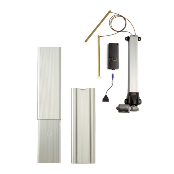
4.0 How it Works ® Movotec Q-Drive Lift Systems are comprised of three major component subsystems; the motor drive, the pump, and the lift cylinders. This section will explain how each subsystem works together to make the lift system extend and retract. ®... -
Page 8: Retraction Cycle
lift cylinders causing them to extend. The gear motor will automatically shut off once the programmed pump upper limit is reached. ® 4.2 Retraction Cycle (Refer to Movotec Q-Drive Schematic on page 7) When the motor switch “DN” arrow button is depressed, the 24VDC gear motor shaft begins to rotate in a (CW) clockwise direction. - Page 9 (J) Motor Cable (Not Shown) • If the lift system is damaged or any component is missing, please contact ® Suspa Incorporated to resolve the issue. • Dispose of the all packaging materials in an ecologically sound manner. P/N: 670-00029A...
-
Page 10: Lift System Specifications
6.0 Lift System Specifications The “A”, “B”, “L”, and “Z” dimensions shown in the table and drawings below vary depending on the system lift capacity and the adjustment range of the selected system. US System Part Numbers Motor Driven Pump ATU Assembly Lift System Adjustment... -
Page 11: Motorized Pump Specifications
6.2 Motorized Pump Specifications ® The Movotec Q-Drive gear motor used with the motorized pump shown below is rated for 24 volts DC. The no-load speed of the gear motor is 160 rpm. The no-load current is 3A. The maximum rated operating torque is 62 lb-in (7N-m). 6.3 ATU Specifications P/N: 670-00029A 2/17/12... -
Page 12: Motor Controller Specification
6.4 Motor Controller Specification Motor Controller Parameter Specification 120V / 50-60Hz (US) Supply Voltage / Frequency 230V / 50-60HZ (Europe) <0.7W Standby Power Consumption Switch Operating Voltage / Current 5VDC / 150mA Hall Sensor Operating Voltage / Current 5VDC / 150mA Operating Temperature Range 32º... -
Page 13: Surface Mount Switch Specifications
United States and Canada shown below (Reference: UL File #258745). CE Information All known, relevant EU guidelines were observed and applied in the design and manufacture of this product. For detailed information on the relevance of CE to ® ® Movotec , please contact Suspa Incorporated. P/N: 670-00029A 2/17/12... -
Page 14: Installation Instructions
® Please note that the Movotec ATU Workstation Kit is not included with system. ® ® Contact Suspa Incorporated for Movotec ATU Workstation Kit ordering information. FOLLOW ALL SAFETY INSTRUCTIONS CONTAINED IN SECTION 3.0 OF THIS MANUAL BEFORE INSTALLING THIS PRODUCT. FAILURE TO... -
Page 15: Typical Installation
7.2 Typical Installation ® The typical installation for the Movotec ATU Workstation Kit is shown below. The installation configuration may vary depending on the brackets, hardware, and/or other structural components used. P/N: 670-00029A 2/17/12... -
Page 16: Foot Bracket Installation
7.3 Foot Bracket Installation • Install M10 washer onto glide thread. • Insert glide thread into hole at end of foot bracket. • Fasten glide to foot bracket using M10 washer and M10 hex nut. Repeat for each glide and foot bracket. P/N: 670-00029A 2/17/12... - Page 17 • Insert end plugs into open ends of both foot brackets using soft-hammer, if necessary. • Align foot bracket with ATU bottom in the desired mounting configuration, cantilever or centered. Cantilever Configuration Centered Configuration • Fasten foot bracket to bottom of ATU using (2) 5/16”-18 thread forming screws. Please note that the function of the thread forming screw is to cut threads into the ATU as the screw is driven into the material.
- Page 18 • Insert hole plug into unused mounting hole. • Repeat foot bracket installation procedure for second foot bracket. When fastening second foot bracket to ATU, make sure that tubing cutout is facing inwards in relation to the other ATU. Cantilever Configuration Shown P/N: 670-00029A 2/17/12...
-
Page 19: Cross Beam Installation
7.4 Cross Beam Installation • Fasten cross beam bracket to cross beam using (2) #14-3/4 tapping screws. The tapping screws require a #3 Phillips drive style. Please note that the function of the tapping screw is to cut threads into the cross beam as the screw is driven into the material. - Page 20 • Position ATU legs as shown below. • Align and insert cross beam bracket hex nuts into ATU T-Slot. Repeat cross beam installation on second ATU. • Position cross beam assembly at desired mounting height. The recommended position is 400mm (15.7 in.) from the top of the ATU to the centerline of the cross beam.
-
Page 21: Lift Cylinder & Top Bracket Installation
• Fasten cross beam to ATU legs tightening the (4) flat head screws on the cross beam brackets. 7.5 Lift Cylinder & Top Bracket Installation Before installing the lift cylinders and top brackets, it is recommended that the pump be securely positioned in between the ATUs. - Page 22 • Orient cylinder head so that tubing is aligned with ATU tubing cutout as shown. • Align top bracket with top of the ATU in the desired mounting configuration, cantilever or centered. Insert cylinder head into top bracket mounting hole as shown.
-
Page 23: Work Surface Installation
• Fasten top bracket to ATU using (2) 5/16”-18 thread forming screws. The function of the thread forming screw is to cut threads into the ATU as the screw is driven into the material. Cantilever Configuration Shown • Repeat top bracket installation procedure for second top bracket. 7.6 Work Surface Installation •... -
Page 24: Motorized Pump Installation
® minimum hydraulic tubing bend radius of 2 in. (51mm) to be maintained. Suspa Incorporated offers a black thermoformed plastic motor cover to further protect the gear motor and cable connections from possible damage. -
Page 25: Motor Controller Installation
In addition, the motor controller should be placed so that it is ® in relatively close proximity to the gear motor. If this is not possible, Suspa Incorporated offers motor extension cables to make up the difference. These cables can be purchased on our website at http://movotec.com. -
Page 26: Motor Controller Cable Connections
• Align the switch body with front edge of the work-surface. Mark and prepare two holes in the locations provided in the switch enclosure. • Using the appropriate screws, mount the switch to the work-surface taking special care not to over tighten the screws. While (2) mounting screws are included with the switch, ensure they will work for the particular application before using to mount switch. - Page 27 • The switch plug has an arrow to indicate proper connection alignment. This arrow must face away from the work-surface and toward their corresponding connection port. To make the controller connections: • Connect the black motor cable plugs in to their respective (M1) and (M2) motor ports.
-
Page 28: Hydraulic Tubing And Cable Management
Take special care not to damage flexible tubing during this operation. • While it is recommended to coil up excess tubing when hydraulic tubing lengths ® are too long, the lines can be shortened. Contact Suspa Incorporated for detailed ®... -
Page 29: Operation Instructions
8.0 Operation Instructions FOLLOW ALL SAFETY INSTRUCTIONS CONTAINED IN SECTION 3.0 OF THIS MANUAL BEFORE OPERATING THIS PRODUCT. FAILURE TO FOLLOW THE INSTRUCTIONS IN THIS MANUAL COULD RESULT IN FIRE, PROPERTY DAMAGE, ELECTRIC SHOCK, PERSONAL INJURY OR DEATH. ® Movotec systems can lift relatively large loads, lasting for many years, as long as they ®... -
Page 30: Connecting To Power
If the lift system does not start promptly and operate as explained after the first operation, perform the System Reset Procedure in Section 8.8 of this manual. If the problem cannot be easily corrected, disconnect the system from power ® immediately and contact Suspa Incorporated technical support. ® ®... - Page 31 If technical support is needed, or any questions exist before operation, system information can be found using the product labels located on the side of the pump (reference photographs below). ® Do not dismantle the system unless authorized by Suspa NOTICE Incorporated. Attempting to repair the system or system ®...
-
Page 32: System Extension Cycle
8.4 System Extension Cycle Depress the “up” arrow button on the surface mount switch. Continue holding the “up” arrow button until the workstation has reached the desired height or the upper limit is reached. 8.5 System Retraction Cycle Depress the “down” arrow button on the surface mount switch. Continue holding the “down”... -
Page 33: Deceleration Zone
intermittently and is rated for a 10% duty cycle. This means that if the lift system activated for 1 minute, it must be at rest for at least 9 minutes before the next operation. It is also important to note that the maximum system on-time is 1 minute. The duty cycle has been established to prevent the gear motor and motor controller electronics from overheating. -
Page 34: Limit Alteration Instructions
3.) The system is behaving unusually. Although it is not very common, a power outage or brown-out condition can cause a motor controller to lose its programmed position. If this happens, the motor may move in one revolution increments in one or both directions. To remedy this problem, perform the system reset procedure below. -
Page 35: Troubleshooting
Motor Controller in Reset Mode Perform “System Reset Procedure” in Section 8.8. Problem: Uneven lift cylinder retraction. Possible Causes Recommended Solutions ® Add load to system. Contact Suspa Incorporated Insufficient Lift Cylinder Load for tube shortening instructions. ® Flexible Tubing Lengths Too... -
Page 36: Inspection And Maintenance
10.0 Inspection and Maintenance FOLLOW ALL SAFETY INSTRUCTIONS CONTAINED IN SECTION 3.0 OF THIS MANUAL BEFORE PERFORMING INSPECTION AND MAINTENANCE PROCEDURES ON THIS PRODUCT. FAILURE TO FOLLOW THE INSTRUCTIONS IN THIS MANUAL COULD RESULT IN FIRE, PROPERTY DAMAGE, ELECTRIC SHOCK, PERSONAL INJURY OR DEATH. ®... -
Page 37: Warranty
® the item by Suspa Incorporated or, if applicable, by Suspa Incorporated’s supplier and if ® the Buyer returns the item to Seller within that period, F.O.B. Suspa Incorporated’s plant ® ® in Grand Rapids, Michigan, then Suspa Incorporated shall, at Suspa Incorporated’s... -
Page 38: Replacement Parts
- Displaying work-surface height in standard inch or metric units - Shortening or lengthening hydraulic tubing lengths ® Please contact Suspa Incorporated or view our website for more detailed information. 14.0 Disposal Dispose of the lift system components in an ecologically sound manner, separating plastic, electronic components, mechanical components, and hydraulic fluid.
Need help?
Do you have a question about the MOVOTEC Q-Drive ATU and is the answer not in the manual?
Questions and answers