
Related Manuals for Parker ViX250AH


Summary of Contents for Parker ViX250AH
- Page 1 ViX250AH & ViX500AH Digital Servo Drive User Guide Part No: 1600.320.01 August, 2003 (For software revision 2.0 onwards)
- Page 2 The information in this user guide, including any apparatus, methods, techniques, and concepts described herein, are the proprietary property of Parker Electromechanical Division or its licensors, and may not be copied, disclosed, or used for any purpose not expressly authorised by the owner thereof.
- Page 3 Product Type: ViX250AH, ViX500AH The above product is in compliance with the requirements of directives • 73/23/EEC Low Voltage Directive • 93/68/EEC CE Marking Directive • 89/336/EEC Electromagnetic Compatibility Directive Provided the installation requirements described in this user guide are met, and there are no special requirements of...
- Page 4 Contact Addresses For engineering For engineering assistance in Europe: assistance in Germany Parker Hannifin plc Parker Hannifin GmbH Electromechanical Electromechanical Division - Digiplan Division - Hauser 21 Balena Close P. O. Box: 77607-1720 Poole, Dorset Robert-Bosch-Str. 22 England, BH17 7DX...
-
Page 5: Table Of Contents
UL Listing, Classification or Certification. User Guide Issue Change Summary This user guide, version 1600.320.01, is the first version of the ViX250AH/ViX500AH Digital Servo Drive. When a user guide is updated, the new or changed text is differentiated with a change bar in the outside margin (this paragraph is an example). - Page 6 VIX AH SERVO DRIVE USER GUIDE Latest Changes Sheet This page lists important changes occurring immediately before publication or between issue updates:...
-
Page 7: Introduction
1. INTRODUCTION 1. Introduction Product Description Available in two power ranges, these digital servos use field-oriented control technology to give enhanced dynamic performance with improved efficiency. Housed within an extremely compact case, the drives are suitable for either direct panel or DIN rail mounting. Using full PWM control with sinusoidal commutation, the two versions of power stage can have continuous current ratings of 2.5A and 5A at motor bus voltages up to 80V. - Page 8 Digital servo drives are available in two power versions. Table 1-1 lists the possible combinations: Product Code Description ViX250AH 250VA Servo with high resolution encoder feedback ViX500AH 500VA Servo with high resolution encoder feedback Table 1-1. ViX250/ViX500 Digital Servo Drive Options...
- Page 9 1. INTRODUCTION Fit Kits Two fit kits are available for ViX drives: 1. VIX-KIT required if you do not purchase motor cables 2. VIX-KIT-NFB required if you do purchase motor cables VIX-KIT VIX-KIT-NFB Part Number Quantity Description Part Number Quantity Description 1650.937.01 Information 1650.937.01...
- Page 10 However, to gain a more in-depth understanding of drive applications and motion control, consider attending one of our world-wide Customer Specific Training Workshops. Details of European based courses are on our web site (www.parker-emd.com) under Sales & Services, Training. Examples of previous courses that have proved to be of benefit include: Use and programming of the DIN rail H &...
-
Page 11: Mechanical Installation
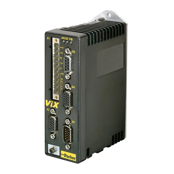
2. MECHANICAL INSTALLATION 2. Mechanical Installation Installation Requirements Environment ViX drives operate in a temperature range of 0° to 40°C with natural convection, or 50°C Max with forced-air cooling (see Hardware Reference), at normal levels of humidity (5-95% non-condensing). The drives can tolerate atmospheric pollution degree 2, which means only dry, non-conductive pollution is acceptable. - Page 12 VIX AH SERVO DRIVE USER GUIDE Drive Dimensions ViX250 and ViX500 drives share the same dimensions, shown in Figure 2-1. 98.5 (with connector) HVSTFB 88,1 Figure 2-1. ViX250 & ViX500 Dimensions...
- Page 13 2. MECHANICAL INSTALLATION Drive Mounting Options If you require a DIN-Rail mounting ViX drive use the DIN-Rail clip adapter bracket shown in Figure 2-2. 16mm Viewed from the back of the DIN rail Allow 10mm for release Figure 2-2. DIN-Rail Adapter Bracket Remove the panel mounting plate from the back of the drive and attach the bracket to the back of the drive using the screws provided.
- Page 14 VIX AH SERVO DRIVE USER GUIDE Motor Mounting Mechanical Considerations Keep motors securely fixed in position at all times. Do not test a motor/drive combination without first securing the motor – see the Safety Warning at the front of this user guide. CAUTION –...
-
Page 15: Electrical Installation
3. ELECTRICAL INSTALLATION 3. Electrical Installation Installation Safety Requirements ViX drives meet the requirements of both the European LVD & EMC directives when installed according to the instructions given within this section. It is recommended the drive be installed in an enclosure to protect it from atmospheric contaminants and to prevent operator access while it has power applied. - Page 16 Figure 3-1. X1 Power Connections WARNING – Possible drive damage If you use Parker XL Series stepper drives do not attempt to use any power wiring harness taken from an XL drive. Although the same mating connector is used for both an XL and a ViX, the ViX wiring is the reverse of the XL and the wrong wiring connection will damage the drive.
- Page 17 3. ELECTRICAL INSTALLATION 11 Supply Requirements Power the ViX drives from DC supplies as specified below: Volts Drive Type DC Supply Voltage between DC+ and DC- ViX500 48V to 80V (recommended) ViX250 24V to 80V Table 3-1. Drive Supply Voltages WARNING The drive HV supply input is not reverse polarity protected.
- Page 18 VIX AH SERVO DRIVE USER GUIDE Power Supply Options Using the previous section, estimate the power required for a single drive or for a group of drives. A set of torque curves (Figure 3-2) for various motor/drive combinations can be used for calculating an applications likely power requirements.
- Page 19 3. ELECTRICAL INSTALLATION 13 XL-PSU Power Supply The XL-PSU is a 250W, power factor corrected, switched mode power supply. Designed for direct operation from world wide single phase AC input voltages, the supply is capable of powering up to two ViX250 drives without the need for an EMC mains input filter. The use of the XL-PSU offers the following benefits: •...
- Page 20 VIX AH SERVO DRIVE USER GUIDE XL-PSU Supply/Drive Connections When used to supply up to two drives the power supply can be wired as shown in Figure 3-3. Mininum spacing 10 mm between drives & PSU +DC (80V) EXT. BRAKING RES. If the supply is positioned this side of the drive +24V...
- Page 21 3. ELECTRICAL INSTALLATION 15 XL-PSU Mounting Information Mount the supply vertically, near the drives it will supply. Both the top 4.5mm diameter fixing hole and the bottom two 4.5mm width fixing slots should be used. Allow a minimum free space of 50mm both below and above its case and 10mm free space on both sides.
- Page 22 VIX AH SERVO DRIVE USER GUIDE PL1100 Power Supply General Description The PL1100 is a linear power supply with a rated output of 1120W (80V/14A) for use with ViX and XL series drives. The supply requires a suitably rated transformer supplying 50V AC RMS for the HV and 20V AC RMS for the +24V DC.
- Page 23 PL1100 EMC Installation Guidelines These EMC installation recommendations are based on the expertise acquired during the development of compliant applications, which Parker believes are typical of the way, a PL1100 may be used. Provided you have no special installation requirements or untypical operating environment requirements, PL1100 power supplies will conform to current EMC Directives.
- Page 24 VIX AH SERVO DRIVE USER GUIDE Mounting resin filled centre, drilled to accept an 8mm mounting screw. See note 1, over the page. +24V CAUTION Risk of electric shock. High voltage remains on terminals REGEN after power is removed. Allow 5 minutes for capacitors to discharge.
- Page 25 • Encoder feedback 71-021124-XX Once again XX defines the length in feet. Should you require a BE or SM servo motor with a mechanical brake, please contact Parker-EMD. See the front of this user guide for contact details.
- Page 26 Note: The cable braiding is folded back over the outer insulation of the motor cable to give a larger diameter contact area and a mechanically strong fixing. The following P-clips sizes are available: Size Parker part number Comments 12.3mm ID 4216.103...
- Page 27 3. ELECTRICAL INSTALLATION 21 15-way D- Encoder type pin reference Inc Enc Z+ Inc Enc Z- 3 (twin) Reserved 5 (twin) +5V output Motor overtemp- Inc Enc A- Inc Enc A+ Comm f-b A0 Motor Overtemp+ Inc Enc B- Inc Enc B+ Comm f-b A1 Comm f-b A2 Reserved...
- Page 28 VIX AH SERVO DRIVE USER GUIDE 150mm FEEDBACK LIMITS MOTOR TO CONNECTOR X5 Figure 3-8. Position of absorbers & motor wiring details There must be no break in the 360° coverage that the screen provides around the cable conductors. Use of a through connector must retain the 360° coverage, possibly by the use of an additional metallic casing where it passes through the bulkhead of the enclosure.
- Page 29 They therefore act like a high impedance in this waveband. Produced by Parker Chomerics, the recommended component is suitable for use with cable having an outside diameter up to 10mm. The specification is as follows: Chomerics part number H8FE-1115-NC (Parker part number 0313.020)
- Page 30 VIX AH SERVO DRIVE USER GUIDE Motor Selection and Set Up Generally, a servo motor is selected together with a drive based on the required speed/torque performance suitable for the intended application. The ViX product catalogue carries details of the performance of the drive when used with a range of recommended servo motor types.
- Page 31 3. ELECTRICAL INSTALLATION 25 Figure 3-9. EASI-V Custom Motor Configuration Window Motor the general name/number for the motor. Nominal continuous current rating of the motor in Amps RMS. current (0.1 to 14.4) Number of number of motor poles for a rotary servo (2 pole/pairs = 4 motor poles, poles so enter 4).
- Page 32 VIX AH SERVO DRIVE USER GUIDE The Optional Parameters Tab Selecting the optional parameters tab gives you access to the screen shown in Figure 3-10. Figure 3-10. EASI-V Custom Motor Optional Parameters...
- Page 33 3. ELECTRICAL INSTALLATION 27 Motor Related System Variables Two-system variables control the current supplied to the motor from the drive. Current Clamp (CL) limits the current output of the drive to protect low current motors or to set a particular torque level, and Peak Current (PC) can allow a controlled boost of motor current when required.
- Page 34 VIX AH SERVO DRIVE USER GUIDE Control of I t Parameters The drive internal I t parameters are always enabled and cannot be adjusted by the user. However, the motor I t settings can be influenced by the choice of parameters used for the MOTOR command.
- Page 35 3. ELECTRICAL INSTALLATION 29 Plots of I t Against Drive Current The following graphs plot drive current against I t time in seconds for a moving and stationary motor for both power versions of the drive. ViX250 I t function - moving 10 11 12 13 14 15 16 17 18 19 20 Time to trip I t circuit in seconds...
- Page 36 VIX AH SERVO DRIVE USER GUIDE ViX500 I t function - moving 10 11 12 13 14 15 16 17 18 19 20 Time to trip I t circuit in seconds Figure 3-13.ViX500 I t function - moving ViX500 I t function - stationary 2 2.2 2.4 2.6 2.8 3 3.2 3.4 3.6 3.8 4...
- Page 37 3. ELECTRICAL INSTALLATION 31 A range of mating connectors Communications are supplied, depending Function upon the type of fit-kit Reserved ordered. Drive reset RS232 GND RS232 Rx RS232 Tx Reserved RS232 Tx (D loop) do not connect Power Earth +5V output Power &...
- Page 38 X1. A brake connection is also provided via X1 pin1. Connector Type The mating connector for X1 is a Wieland type 213B/, part number 25.323.4053.0 (Parker part number 0405.811). An approval marked version of this connector has the part number 25.323.1053.0.
- Page 39 3. ELECTRICAL INSTALLATION 33 Motor Brake Control Wiring Certain motors used with the ViX drives can be fitted with a holding brake. This enables vertical (Z-direction) loads to be held whilst the motor is de-energised. All brakes are fail-safe, that is you need to apply power to the brake to keep it disengaged. Removing power from a brake will engage or activate the brake preventing further shaft motion.
- Page 40 VIX AH SERVO DRIVE USER GUIDE X2 Connector X2 provides the primary input connections for the motor feedback device. Connector Type Connector type is a high-density 15-way D-type socket. Connector Pin Out Connector Encoder Pin X2 Incremental enc. Z+ Incremental enc. Z- reserved +5V output Incremental enc.
- Page 41 Maximum loading 350mA TOTAL, using the above connections. Motor Overtemperature Sensor The motor overtemperature switch input is compatible with thermal switches used in Parker SMB, SME, SM and BE servo motors. The input requires a normally closed switch to be connected to GND on X2 pin 3 or 6.
- Page 42 VIX AH SERVO DRIVE USER GUIDE Connector Pin Out Connector Pin X3 Function Reserved drive reset RS232 GND RS232 Rx RS232 Tx Reserved RS232 Tx (D loop) Do not connect +5V output Table 3-9. X3 RS232 Connections Baud Rate Use system variable BR to alter the baud rate of serial communications. Any change made to the baud rate will only take effect following a save (SV) and system reset (Z) or power cycle.
- Page 43 3. ELECTRICAL INSTALLATION 37 Reset to RS232 Mode To reset the drive to RS232 mode and to return to factory settings, remove power from the drive, connect X3 pin2 to GND and restore power. CAUTION This will erase ALL of your user settings and programs in volatile memory. The non- volatile memory will not be overwritten until a save command is issued.
- Page 44 Use the RJ45 connectors X6 and X7 to inter-connect drives, see RS232 Daisy Chain later in this section. RS232 Connecting Leads RS232 cables can be ordered from Parker EMD. Various lengths are available as listed in Table 3-10. Part Number...
- Page 45 3. ELECTRICAL INSTALLATION 39 X4 Connector Connector X4 gives access to the following encoder input and output signals and the differential analogue inputs. Input and output connections are dependent upon the state of system variables EO and EI. Connector Type Connector type is a high-density 15-way D-type socket.
- Page 46 VIX AH SERVO DRIVE USER GUIDE Encoder Input/Outputs Figure 3-18 shows the circuit details of the simulated encoder inputs and outputs. Note: /Z, Z channels have the same I/O circuits as the /A, A & /B, B channels. Encoder inputs Encoder outputs using 26LS32 quad differential using 26LS31 quad differential...
- Page 47 3. ELECTRICAL INSTALLATION 41 Figure 3-20 shows the input characteristic. Velocity (rps) Commanded velocity Dead band -10V Volts +10V Figure 3-20. Analogue Differential Input Characteristic Fault Output The fault output is an independent NPN open-collector output, which is normally ‘low’ active ‘high’.
- Page 48 VIX AH SERVO DRIVE USER GUIDE _______ Energise/Energise You can energise the drive by allowing this input pin to float high ‘1’ or by linking the pin to zero volts, depending upon the input’s polarity. System variable ES controls the polarity of this input.
- Page 49 3. ELECTRICAL INSTALLATION 43 When driven from a high logic level 24V source, a logic ‘1’ (+24V logic) will engage the brake and a logic ‘0’ (transistor off) will release the brake. When driven from a high logic level 24V sink, a logic ‘1’ or a high impedance state (transistor off) will engage the brake and an active pull-down to a logic ‘0’...
- Page 50 VIX AH SERVO DRIVE USER GUIDE Analogue Monitor The analogue monitor output on X5 pin 15 can be used to examine torque, velocity or a ramp test signal depending upon the setting of system variable AM. Figure 3-23 shows the circuit of the output.
- Page 51 3. ELECTRICAL INSTALLATION 45 FEM1 CAT5 cable colours CANopen/RS485 RX+/TX+ RS485 White/Orange RX-/TX- RS485 Orange Reserved White/Green RS232 Gnd Blue RS232 Gnd White/Blue Reserved Green RS232 Tx White/Brown Rs232 Rx Brown RX+/TX+ RS485 White/Orange RX-/TX- RS485 Orange Reserved White/Green RS232 sense Blue RS232 Gnd White/Blue...
- Page 52 VIX AH SERVO DRIVE USER GUIDE Communication Daisy Chain Drives can be ‘daisy-chained’ for RS232 operation as shown below. Using this arrangement the drive connected to the controlling PC, via its front panel D-type connector, becomes axis #1. To automatically assign addresses, connect all power, motor, feedback and communication cables then power-up all the drives, see ‘#’...
- Page 53 3. ELECTRICAL INSTALLATION 47 RJ45 Connecting Leads RJ45 link cables can be ordered from Parker EMD. Various lengths are available as listed in Table 3-14. Part Number Length VIX-RJ45-0025 0.25m VIX-RJ45-0050 0.5m VIX-RJ45-0075 0.75m VIX-RJ45-0100 1.0m VIX-RJ45-0200 2.0m Table 3-14. RJ45 Connection Lead Types...
- Page 54 VIX AH SERVO DRIVE USER GUIDE...
-
Page 55: Control Of Vix Drives
4. CONTROL OF VIX DRIVES 49 4. Control of ViX Base Drives Overview This section introduces you to the operation of the ViX base servo drive. The drive uses a sub-set of ViX commands and system variables to support the drive when connected to an external controller or an analogue input. - Page 56 VIX AH SERVO DRIVE USER GUIDE Table of System Variables Table 4-1 lists system variables in alphabetic order together with their read/write status and range of values stored. Name Range/default value Analogue 0 to +255, default = 0 Deadband Analogue Input N -2047 to +2047 Analogue Monitor 0 = torque monitor (default)
- Page 57 4. CONTROL OF VIX DRIVES 51 Name Range/default value Integrator Gain 0 to 1023 default depends on motor type (steady state) Proportional Gain 0 to 1023 default depends on motor type (stiffness) Velocity feedback 0 to 1023 default = 5 Gain (damping) Input/Output Input pull-up/down, output source/sink configuration...
- Page 58 VIX AH SERVO DRIVE USER GUIDE AB, AI and AO Description AB controls the dead band and AO the offset of the differential analogue speed/torque control input. See Differential Analogue Input in the Electrical Installation section. AM Description Use output 4 (X5 pin 15) to output an analogue DC voltage between +10V and –10V to represent the velocity or torque being generated by the drive, depending upon the setting of system variable AM.
- Page 59 4. CONTROL OF VIX DRIVES 53 DF Description See drive fault bit description in Reporting the Status of Variables. EO Description Use encoder outputs (connector X4) to supply a step-direction or step-up/step-down signal for use by another drive. System parameter EO determines the output as defined in Table 4-2.
- Page 60 VIX AH SERVO DRIVE USER GUIDE also serves to average the effects of the digital control loop, reducing the jitter at standstill and the audible noise. The value of FT should be kept as low as possible. The arbitrary units used to set the value of FT cannot be directly related to any time value. GF Description The opposing action of proportional and velocity gains result in a position error which depends on speed.
- Page 61 4. CONTROL OF VIX DRIVES 55 PC Description See Motor Related System Variables in Electrical Installation. PE Description PE reports the position error, that is, the difference between PT and PA. PF Description PF reports the position fed-back by a remotely mounted encoder for following applications. RV Description Reports the revision of software being used by the controller.
- Page 62 VIX AH SERVO DRIVE USER GUIDE Reporting the Status of Variables By examining Table 4-5 you can see that most system variables take a numerical value or record a simple ON/OFF state (0 or 1 Flags). Certain variables perform a reporting function that provides you with information on the status of the controller and any drive faults present in the hardware or user program code.
- Page 63 4. CONTROL OF VIX DRIVES 57 Fault Status Reporting Faults are classified into two groups: Drive Faults DF (hardware faults present in the drive) User Faults UF (user program faults) Drive Faults Hardware drive faults cause the drive output stage to turn OFF (de-energised). This will cause the Drive LED to turn RED.
- Page 64 VIX AH SERVO DRIVE USER GUIDE Bit Number Stop Type DF Information Composite fault (anything that causes a drive fault) +/-15V supply rail Motor HV under-voltage trip point reached Motor HV over-voltage trip point reached V I/O under-voltage trip point reached V I/O over-voltage trip point reached Encoder/Auxiliary 5V under voltage trip Impending power loss...
- Page 65 4. CONTROL OF VIX DRIVES 59 User Faults Programming errors, such as issuing a GO command when the drive is de-energised can cause user faults. The report uses a 32-bit word format the same as Drive Faults. Performing a read UF command will report the current state of any User Faults listed in Table 4-6.
- Page 66 VIX AH SERVO DRIVE USER GUIDE Servo Control Loop d/dt Position Torque Demand Demand ∫ d/dt Position Feedback Figure 4-1. ViX Servo Control Loop...
- Page 67 4. CONTROL OF VIX DRIVES 61 Controlling the Drive’s Mode of Operation Mode Operation of the ViX base drive is possible in three different modes, controlled by the M (Mode) command. These are: • Base servo position mode • Base servo torque mode •...
- Page 68 VIX AH SERVO DRIVE USER GUIDE Connections 6K Drive Description ViX X4 Description connector connector Step + Direction + Fault Fault Shutdown (NO) Energise Step - Direction - B – *13/14 Isolated Gnd/Shutdown (COM) *Pins 13 and 14 should be connected together at the 6K Table 4-7.
- Page 69 4. CONTROL OF VIX DRIVES 63 Base servo torque/velocity mode This mode uses the servo analogue inputs to control the drive. Figure 4-3 shows a 6K controller, used for control purposes. A double multi-core cable links the 6K and ViX with the connections listed in Table 4-8.
- Page 70 VIX AH SERVO DRIVE USER GUIDE Connections ViX X4 Description 6K connectors Description connector Ana1+ 3 - Drive Command + Ana1- 6 - Drive Command - 9 - Drive Isolated Gnd Fault 5 - Drive Fault A- out 3 - Encoder B- out 5 - Encoder Energise...
- Page 71 4. CONTROL OF VIX DRIVES 65 Torque Mode Commands For the ViX drive issue the following commands: ;Mode Torque 1W(ES,0) ;Energise input active level 1GAINS(0,0,0,0,0) ;Zero all gains ;Save settings A valid MOTOR command is required. All GAINS need to be 0.0 For the 6K4 issue the following commands: AXSDEF1111 All axes are steppers...
- Page 72 VIX AH SERVO DRIVE USER GUIDE Brake Operation ViX drives have the ability to control a motor holding brake via the X1 pin 1 motor brake output. Note, special conditions apply to the brake wiring depending upon the brake supply used, see Motor Brake Control Wiring in the Electrical Installation section.
- Page 73 4. CONTROL OF VIX DRIVES 67 External Brake Control The base drive (AE version) has a dedicated input (X5 pin10) used for external control of the brake. This input can be driven from a high-level logic source or sink, or a low-level logic source, see Brake Input Circuit in Electrical Installation section.
- Page 74 VIX AH SERVO DRIVE USER GUIDE Reset (Z) Issuing a reset will engage the brake, at least momentarily, as the system fails safe. Subsequently, the following will happen: • The brake will remain applied in automatic mode until the drive is re-energised. •...
-
Page 75: Easi-V Software
Note: The information contained within this section applies to Easi-V software version 3.0 or greater. If you have an earlier version of Easi-V software please request the latest version from Parker EMD using the contact numbers given at the beginning of this user guide or download a copy from our web-site (www.parker-emd.com). - Page 76 Easi-TOOLS in the directory of your choice. The default directory is c:\program files\parker\EasiV in the UK, but the exact path name is country dependent, other buttons are described within the dialogue box, see Figure...
- Page 77 5. EASI-V SOFTWARE 71 Figure 5-1. Choosing Where to Install Easi-V 6. Once you have selected a destination for Easi-V or have decided to use the default directory, select NEXT to begin file transfer. 7. Once Easi-V has been loaded, the screen will display a message dialogue box, stating ‘Setup is complete.
- Page 78 Selecting Product from the Utilities menu will also display the product selection screen. Selecting OK will display the main application window, entitled ‘Parker Hannifin EMD – Easi-V’, and seven pull-down menus become available: File, Edit, Search, Terminal, Utilities, Windows, Help The majority of options available within each menu are familiar to Window™...
- Page 79 5. EASI-V SOFTWARE 73 Menu Overview Filing Operations File Creates a new editor file, or .prg program file Opens an existing editor file or program Save an editor file Save an editor file specifing the file name Print the editor file or contents of terminal buffer Close current active window Exit Easi-V Editing Operations...
- Page 80 Program help facilities Help Open help file at the main contents (start) Prompt for topic string and search help file Open help for individual EASI-V commands Visit Parker web-site E-mail Parker technical support E-mail Parker sales support EASI-V version number and copyright...
- Page 81 5. EASI-V SOFTWARE 75 Terminal Menu Selections Terminal menu selections control the setup and configuration of communication between a PC and drive. Communicating with a Drive The default settings of a new drive from power-up are RS232 communications with an address setting of #1.
- Page 82 VIX AH SERVO DRIVE USER GUIDE Select the required configuration and, click OK. Then, again from the Terminal menu select Connect to start communications. Every time Connect is issued the communications link is tested to establish it is working correctly and the message box ‘Testing communications integrity’...
- Page 83 5. EASI-V SOFTWARE 77 Utilities Menu Selections Utilities menu selections control the way drives are setup and configured for use with a particular motor type. The menu offers two levels of setup, depending upon the skill and experience of the operator. •...
- Page 84 VIX AH SERVO DRIVE USER GUIDE From the drop- down menu select your motor type or perform a custom set-up. Click ‘Next>’. Select the operating mode of the drive and the direction of rotation required for a rotary motor. Click ‘Next>’.
- Page 85 5. EASI-V SOFTWARE 79 Use this screen to adjust the value of the Peak Current ration (PC). For a pre-defined motor type use the default value displayed. Keep the Current Clamp (CL) value as 100%. Click ‘Next>’. This screen allows adjustment of the drive’s gain parameters.
- Page 86 VIX AH SERVO DRIVE USER GUIDE Use this screen to configure the brake input to match the output generating the brake signal. The screen also allows selection of the type of simulated encoder output or input required. Click ‘Next>’. • High logic level 24V source (IC = 256) [upper box ticked lower blank] (default) •...
- Page 87 5. EASI-V SOFTWARE 81 The general configuration screen allows adjustment of motor brake settings, communication settings, analogue input control and defines what is monitored by the monitor output. The state of system variable ES can also be set via this screen.
- Page 88 VIX AH SERVO DRIVE USER GUIDE Servo Setup This facility gives easy access to setting system variables in a more direct manner than Guided Servo Setup. Figure 5-5 shows a sample screen. Figure 5-5. Other Tab of Servo Setup The buttons displayed along the base of this screen can be used as follows: Upload retrieves the current settings for the selected axis Download updates the current axis with your latest changes Open opens a stored .cfg file...
- Page 89 5. EASI-V SOFTWARE 83 Status The Utilities menu axis Status provides a convenient method of examining the double word status bits. The tool gives access to the status of User Faults, Status bits and Drive Faults using a series of tabs, as shown in Figure 5-6. Figure 5-6.
- Page 90 VIX AH SERVO DRIVE USER GUIDE Help EASI-TOOLS has extensive on-line help facilities, which allows you to search for help on a particular topic either within the main contents or by entering a topic string. All the commands listed within this user guide are available on-line by selecting Controller Commands from the Help menu.
-
Page 91: Command Reference
6. COMMAND REFERENCE 6. Command Reference Command Description Each command has a simple 1 to 7 character name usually an abbreviation of its full descriptive title. Listed commands are in alphabetic order with any non-alphabetic symbols appearing last. Each individual description will include a one-line header giving the abbreviated name followed by its full name. - Page 92 VIX AH SERVO DRIVE USER GUIDE A multi-parameter command can take the form shown in Figure 6-2. aGAINS(parameter1,2,3,4,5) Parameters 1,2,3,4 & 5 Command name Address prefix Note: optional parameters are displayed in italics Figure 6-2. Parameter Commands Attention [1] Terminate all commands with a carriage return. A space is not valid. [2] A command must not contain any space characters.
- Page 93 6. COMMAND REFERENCE Immediate Only Immediate only commands are: K, R(UF), R(DF) and R(ST) The controller acts upon these commands as soon as they are received. Immediate or Buffered Immediate or buffered commands are immediate unless command execution is being delayed, in which case the command is buffered.
- Page 94 VIX AH SERVO DRIVE USER GUIDE BRAKE Brake configuration Syntax aBRAKEn(mode,RD,ED) Description is used to release a brake and to cancel any previously selected automatic mode. mode selects the way the brake is used automatic holding brake mode automatic dynamic brake mode external input used for brake (AE variant only) brake modes disabled (default) RD is the time in milliseconds for the brake to release after the drive has...
- Page 95 6. COMMAND REFERENCE GAINS Gain configuration Syntax aGAINS(GF,GI,GP,GV,FT) Issuing a GAINS command with no parameters, produces a verbose list of all Description current gains. Parameters may be set up all together in one command. Alternatively, gains may be individually set/reported by using the read and write variable commands.
- Page 96 VIX AH SERVO DRIVE USER GUIDE Change direction Syntax Units Range of ‘n’ Default See also + or - STATUS Description The H command changes the direction of motion according to a positive demand signal. A blank value following the H command will be reported as an error.
- Page 97 6. COMMAND REFERENCE Kill Syntax Units Range of ‘n’ Default See also OFF, SETUPFB The KILL command will perform the following functions: Description Abort a SETUPFB command. Execute an OFF command Set the fault output This command is used as an immediate stop and does not attempt to control deceleration.
- Page 98 VIX AH SERVO DRIVE USER GUIDE Mode Syntax Units Range of ‘n’ Default See also see below The mode command sets up the mode of operation of the drive. Description The values of n are: P – base servo position mode (step and direction input) T –...
- Page 99 6. COMMAND REFERENCE MOTOR Motor Settings Syntax aMOTOR(Type,Current,Resolution,Max_vel,Thermal_const,Resistance, Inductance,KT) Description This command describes the characteristics of the motor being used to the rest of the drive. The parameters used are: Type – 0 to 65535 number code, which includes pole count, feedback type, brake and any other particular requirements (refer to EASI-V).
- Page 100 VIX AH SERVO DRIVE USER GUIDE Immediate, saved by SV Properties Note [1] If the thermal time constant is set to zero, the I t protection for the motor is disabled. [2] The motor command can take up to 10 seconds to finish execution. [3] The drive will not be allowed to energise without a valid motor command being executed.
- Page 101 6. COMMAND REFERENCE Return to factory settings Syntax Units Range of ‘n’ Default See also aRFS Description Issuing an RFS command initialises the drive to factory default settings. The drive must be de-energised (OFF) for the RFS command to be executed. Immediate, saved by SV Properties Note...
- Page 102 See also aSETUPFB Description For a correctly wired Parker motor, this command is not required. However, when commissioning problems occur with a motor/drive system, the SETUPFB command can be used to troubleshoot motor wiring problems in encoder and resolver units and to temporarily compensate for these errors.
- Page 103 Properties Example 1STATUS ;checking the configuration and state of a drive 1STATUS *ViX500AH-Servo Copyright 2002 Parker-Hannifin *Firmware: REV 2.2D Dec 03 2002 17:11:23 Map No: 114 *Serial number: ..541935.00.1.4. -ViX500xx *Control card revision 2 Servo drive *Power card revision 3...
- Page 104 VIX AH SERVO DRIVE USER GUIDE Save configuration Syntax Units Range of ‘n’ Default See also Description When the SV command is issued, the current drive system variables and configuration are stored in non volatile memory. Following a reset or power- cycle the settings held in the non-volatile memory will be restored into the drive.
- Page 105 6. COMMAND REFERENCE Write system variable Syntax aW(system_variable,value) Description The W command allows you to set a specified system variable to a particular value. Refer to the table of system variables for more information. Immediate not saved by SV Properties Example Set system variable TL (Tracking Limit) to 4000 2W(TL,4000)
- Page 106 100 VIX AH SERVO DRIVE USER GUIDE System Variables Name Range/default value Analogue 0 to +255, default = 0 Deadband Analogue Input N -2047 to +2047 Analogue Monitor 0 = torque monitor (default) Mode 1 = velocity monitor 2 = outputs a triangular waveform –10V to +10V amplitude, with a 1 second period Analogue Offset -2047 to +2047, default = 0...
- Page 107 6. COMMAND REFERENCE Name Range/default value Integrator Gain 0 to 1023 default depends on motor type (steady state) Proportional Gain 0 to 1023 default depends on motor type (stiffness) Velocity feedback 0 to 1023 default = 5 Gain (damping) Input/Output Input pull-up/down, output source/sink configuration Configuration 0, 256 (default) or 257, for brake input only...
- Page 108 102 VIX AH SERVO DRIVE USER GUIDE Drive Faults Bit Number Stop Type DF Information Composite fault (anything that causes a drive fault) +/-15V supply rail Motor HV under-voltage trip point reached Motor HV over-voltage trip point reached V I/O under-voltage trip point reached V I/O over-voltage trip point reached Encoder/Auxiliary 5V under voltage trip Impending power loss...
- Page 109 6. COMMAND REFERENCE Status Bits Bit Number Status Information Motor energised Motor undefined, use MOTOR command Duty cycle too high, excessive motor current (I Tracking limit is greater than max. allowed position error Last SETUPFB command failed In motion, 0 for positive motion, 1 for negative motion Brake applied, goes to a 1 if the brake is engaged User Faults Bit Number...
- Page 110 104 VIX AH SERVO DRIVE USER GUIDE Command List Command Description BRAKE Brake configuration GAINS Gains configuration Change direction Kill Mode Motor settings MOTOR Report system parameter Return to factory settings Setup motor feedback SETUPFB Report status of drive STATUS Save configuration Write system variable Reset...
-
Page 111: Vix Maintenance And Troubleshooting
7. MAINTENANCE & TROUBLESHOOTING 7. ViX Maintenance and Troubleshooting Maintenance ViX drive systems do not require any routine maintenance, but occasional checking of the following points is recommended. Motor inspection Periodically check the motor to ensure that the mounting bolts and couplings are tight. Check that the motor cables are not being damaged by moving parts and are not being pulled or forced into tight bends during machine operation. - Page 112 106 VIX AH SERVO DRIVE USER GUIDE Communication Problems When attempting a Connect from the Terminal menu, if the connection fails with the following error message: Figure 7-1. Communications Failure Error Message Check the following: 1. Ensure the serial port configuration is set correctly in EASI-V and you select the correct serial COM port.
- Page 113 7. MAINTENANCE & TROUBLESHOOTING Drive LED Indicators Colour Function Green HV OK Orange HV OK and feedback fault Feedback fault with no HV Colour Function Green Ready (energised) Orange Drive OK but de-energised Drive fault Colour Function Green Comms OK Orange Comms status Comms fault Figure 7-2.
- Page 114 108 VIX AH SERVO DRIVE USER GUIDE Complete LED Diagnostics An EASI-V version of this table is available for quick on-line viewing. Colour(s) Flash rate Functional description green none motor supply OK orange none motor supply under voltage (<16V) none motor supply over voltage (>96V) no motor supply green...
- Page 115 7. MAINTENANCE & TROUBLESHOOTING Forcing a Hardware RFS Pin 2 of serial communications D-type connector X3 is for use as a hardware method of forcing a return to factory settings. It may be used when it is not possible to perform an OFF or RFS command.
- Page 116 110 VIX AH SERVO DRIVE USER GUIDE Returning the System If a drive module is found to be faulty, you should contact your Parker Automation Technology Centre or the machinery manufacturer who supplied the product. Equipment for repair should NOT be returned directly to Parker without prior authorisation. Repairs will be carried out by Parker but will be processed via your supplier.
-
Page 117: Hardware Reference
8. HARDWARE REFERENCE 8. Hardware Reference Drive Functional Specification – ViX250AH, ViX500AH Parameter Value Maximum output current ViX500: 5A RMS continuous 15A RMS peak (2 seconds max.)* ViX250: 2.5A RMS continuous 7.5A RMS peak (2 seconds max.)* Maximum continuous power drawn from the 6.3A at 80V (500VA) - Page 118 112 VIX AH SERVO DRIVE USER GUIDE Controller Specification Parameter Value Communication Data format 8 data bits, 1 start bit, 1 stop bit, no parity, optional echoback, Xon/Xoff supported Baud rate 9600, or 19,200 Address setting range 1 -255 by software RS232 connection 2 wire plus ground Brake Input...
- Page 119 8. HARDWARE REFERENCE Drive Environment Specification Parameters All drive types Environment Pollution degree 2 Operating temperature range 0 to 40°C ambient for natural convection cooling 40°C to 50°C with forced air cooling of minimum 0.5m/s entering the base of the drive (approximately 3.5m /h or 2cfm airflow through the cabinet)
- Page 120 114 VIX AH SERVO DRIVE USER GUIDE...
- Page 121 APPENDIX A Appendix A Discrete Power Supply Recommendations If the XL_PSU is not being used individual ViX drives can be powered from transformer/bridge rectifier power supplies of the type shown in Figure A-1. This design suggests suitable component values for powering particular drive types, but can be adapted to power more than one drive provided component power ratings are not exceeded.
- Page 122 116 VIX AH SERVO DRIVE USER GUIDE The size of transformer required for a servo drive installation depends very much on the application and on the maximum shaft power delivered by individual motors. It is worth noting that in a one-off or low volume application it is usually preferable to be slightly generous in sizing the transformer, rather than spend a great deal of engineering effort trying to calculate the minimum possible rating.
- Page 123 APPENDIX A Appendix B – Encoder Phasing Encoder Phasing Diagrams for the ViX AH Phasing is shown for clockwise rotation when the motor is viewed from the motor mounting flange. Line voltage W-V is defined as X1 pin 2 with respect to X1 pin 3 Line voltage V-U is defined as X1 pin 3 with respect to X1 pin 4 Line voltage U-W is defined as X1 pin 4 with respect to X1 pin 2 Positive encoder rotation is defined as when incremental encoder channel A leads...
- Page 124 118 VIX AH SERVO DRIVE USER GUIDE...
-
Page 125: Index
INDEX Index Command address requirements, 85 24V supply requirements, 11 label & multi parameter syntax, 86 presentation, 85 reference, 85 A to D converter, 40 simple syntax, 85 AB, AI & AO system variables, 52 Command checking, 87 Absorber ferrite, 23 Command list, 104 AI system variable, 40 Command properties, 86... - Page 126 INDEX menu overview, 73 GV system variable, 54 running, 71 software file size, 69 H change direction, 90 startup, 72 Hardware reference, 111 status reporting, 83 Help menu, 74 uninstall, 72 Housing material, 113 ED operation, 66 Humidity, 113 Edit menu, 73 EI system variable, 53 Electrostatic precautions, 9 I 2 t operation, 27...
- Page 127 INDEX selection, 24 Returning the system, 110 system variables, 28 RFS return to factory settings, 95 wire size, 20 RJ45 connecting leads, 47 Motor inspection, 105 RJ45 patch cables, 47 Motor mounting precautions, 8 RS232 cables, 38 MOTOR settings, 93 RS232 connecting leads, 38 Motors RS232 daisy chain, 44...
- Page 128 INDEX System variables, 49, 85 reading, 49 W write system variable, 99 reporting status, 56 Weight, 113 table of, 50 Welcome box, 70 writing, 49 Windows menu, 74 Windows™, 69 Wire size of motor earth, 28 Temperature Withstanding voltage rating, 115 ambient, 113 storage, 113 Terminal menu, 74...
- Page 129 Found on the title page in the bottom left corner. Your name: Contact number or email address: Description of the error: (Please include page number) Errors can be reported By phone, via a technical Or by email: by Fax: support engineer: +44 (0)1202 695750 +44 (0)1202 699000 support.digiplan@parker.com...
- Page 131 VIX AH SERVO DRIVE USER GUIDE A range of mating connectors Communications are supplied, depending Function upon the type of fit-kit Reserved ordered. Drive reset RS232 GND RS232 Rx RS232 Tx Reserved RS232 Tx (D loop) do not connect Power Earth +5V output Power &...
Need help?
Do you have a question about the ViX250AH and is the answer not in the manual?
Questions and answers