Advertisement
Quick Links
Download this manual
See also:
User Manual
CONTENTS
Revision History..............................................................................
General..........................................................................................
Radio Overview...............................................................................
Software Specification..................................................................
Circuit Description.........................................................................
Semiconductor Data...................................................................
Component Description..............................................................
TM-600 Parts List 1.........................................................................
Tu n i n g De s c r i p ti o n ... ... ... ... ... ... ... ... ... ... ... ... ... ... ... ... ... ... ... . ... ...
Trouble-shooting Flow Chart..................................................
Disassembly and Reassembly for Repair.........................................
Exploded View.............................................................................
TM-600 Parts List 2........................................................................
Packing.......................................................................................
Te r m i na l F u n c ti on ... ... ... ... ... ... ... ... ... ... ... ... ... ... ... ... ... ... ... ... ... ...
PC Board View...........................................................................
Schematic Diagram......................................................................
Block Diagram............................................................................
Specifications............................................................................
第
页 共
页
1
57
Advertisement

Related Manuals for Hytera TM-600


Summary of Contents for Hytera TM-600
- Page 1 Component Description…………………………..………………………… TM-600 Parts List 1…………………………………………………….………… Tu n i n g De s c r i p ti o n … … … … … … … … … … … … … … … … … … … . … …...
- Page 2 Revision History Version Date Contents Revised Parts No. 2006 September Initial release General Manual Scope This manual is intended for use by experienced technicians familiar with similar types of communication equipment. It contains all service information required for the equipment and is current as of the publication date.
- Page 3 (1) Any space containing radio equipment shall be isolated by a seal from the space in which the LP gas container and its fittings are located. (2) Remote (outside) fitting connections shall be used. (3) Good ventilation is required for the container space. Installation Safety Guidelines Do not mount the mobile radio overhead or on a sidewall unless you take special precautions.
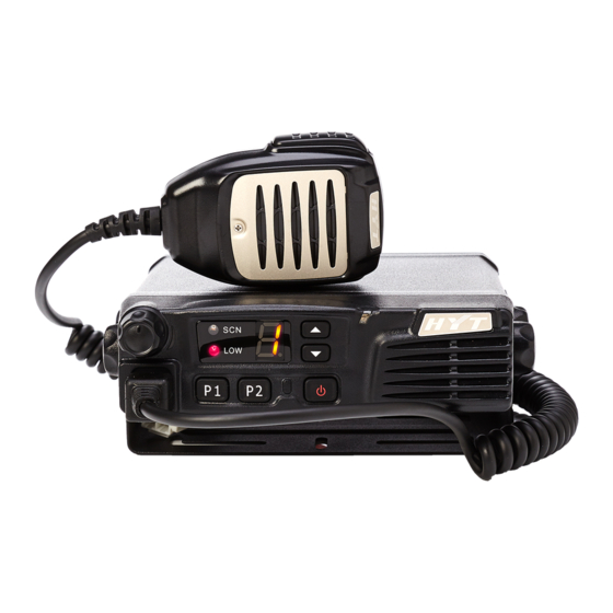
- Page 4 Radio Overview Front Panel Volume Control Knob ① Turn the knob clockwise to Tuning upwords and counter-clockwise downwards. ② LED Indicator and 8-segment Numeric LED Please refer to “LED Indicator and 8-segment Numeric LED” section. Programmable Function Key ([▲] / [▼]) ③...
- Page 5 Rear Panel Overview 15PIN (for external expansion) ① External Speaker Jack ② Used to connect external speaker and only available for the plug of 3.5 mm Power Inlet ③ Adopt HYT-authorized DC power cable and 13.6 V DC power. ④ Antenna Pedestal Used to connect external antenna.
- Page 6 Software Specification . . . . F rame of Radio Modes Conventional Mode User Mode Tuning Mode Model Set Mode Wired Clone Mode Clone Mode Wireless Clone Mode PC Mode Keypad Entry for Mode Startup . . . . Mode Display Operation Remarks...
- Page 7 K ey Assignment . . . . Programmable functional keys [P1]/[P2] and [▲] / [▼]. Key Assignment Settings Display Remarks [P1] CH Number None CH Up CH Number Channel up CH Down CH Number Channle down MONI A: MONI A CH Number Monitor Unmute-Momentary MONI B:...
- Page 8 Scrambler Scrambler CH Number Compander Compander CH Number EmergencyCH Emergency call Number (1- 8) Emergency call [P2] CH Number None CH Up CH Number Channel up CH Down CH Number Channle down MONI A: MONI A CH Number Monitor Unmute-Momentary MONI B: MONI B CH Number...
- Page 9 Compander CH Number Compander EmergencyCH Emergency call Number (1- 8) Emergency call [▲] ( [UP] ) CH Number None CH Up [Default] CH Number Channel up CH Down CH Number Channle down MONI A: MONI A CH Number Monitor Unmute-Momentary MONI B: MONI B CH Number...
- Page 10 EmergencyCH Emergency call Number (1- 8) Emergency call [▼] ( [DOWN] ) Off CH Number None CH Up CH Number Channel up CH Down [Default] CH Number Channle down MONI A: MONI A CH Number Monitor Unmute-Momentary MONI B: MONI B CH Number Monitor Unmute-Toggle MONI C:...
- Page 11 Selected when using palm Hook/Moni Hook test CH Number microphone. Selected when using Moni CH Number desktop microphone. Selector Knob Volume knob CH Number Volume knob Note: the above “CH Number” indicates any number between 1 and 8. P C Mode ....
- Page 12 dealer. P ress [Up] to toggle between Dealer Clone and Factory Clone Mode. “C” or “C.” ) appears on the display when the corresponding mode is selected. U nlike Factory Clone Mode, tuning settings and embedded messages are not ) covered in Dealer Clone Mode.
- Page 13 Note: Clone Mode can be enabled/disabled by your local dealer. Wired clone is accessible only when Clone Mode is enabled. 6. Tuning Mode The operations of Tuning Mode are described as following: Press [P1] to power on the radio. The radio enters Tuning Mode and its LED flashes red )...
- Page 14 Center No signalling . Narrowband . No signalling High No signalling . Center . 100Hz square wave Wideband 100Hz square wave . High 100Hz square wave CDCSS Balance . Medium Center 100Hz square wave . Narrowband Center . 100Hz square wave Center CTCSS: 67.0Hz ....
- Page 15 Medium Center 1KHz . Narrowband Center 1KHz . . No signalling , S Q off Low-medium . No signalling , S Q off frequency RX Sensitivity Center No signalling S Q off . , Medium-high . No signalling , S Q off High No signalling S Q off...
- Page 16 flashes green twice. The selected model number is displayed. P ress [Up]/[Down] to choose model No. 0-4 ) ) P ress [P2] to confirm. LED glows orange and the radio resets; then the radio enters User Mode after reset. Notes: 1.
- Page 17 Circuit Description 1. Frequency Configuration The receiver utilizes double conversion superheterodyne. The first IF is 49.95MHz and the second is 450KHz. The first local oscillator signal is supplied by PLL circuit; and the second (50.4MHz) is generated from the frequency tripling of TCXO (16.8MHz). The PLL circuit generates the frequencies required for transmission.
- Page 18 Fig 1 Receiver Circuit 2.1 RF AMP BPF It consists of BPF (LC resonant circuit where D107, D108 and D109 are located) and RF amplifier (Q111). The range of bandpass frequency is the frequenc range of the radio itself. The signal is filtered by the BPF to eliminate unwanted signals before going to the first mixer.
- Page 19 Fig 2 Transmitter Circuit 3.1 MIC and modulation circuit The audio signal from MIC is amplified by IC405 before being pre-emphasized and encoded by IC401. The output audio is added into signalling and then is fed through VCO for modulation. RF Driver and Final Power Amplification Circuit The TX-RF signal outputted from Q703 in VCO circuit is amplified by Q101, driver Q110 and Q109, The amplified signal is then fed to IC101 (final PA) and passes through LPF...
- Page 20 In transmit mode, IC120 transmits the frequency data to PLL IC. Q704 is turned on to activate TX VCO. The outputted signal is amplified by Q703, Q102, and then divided by PLL IC into 2.5KHz, 5KHz or 6.25KHz signal. The divided signal is compared with 2.5KHz, 5KHz or 6.25KHz reference signal from 16.8MHz crystal oscillator (2.5 PPM frequency stability) in the phase comparator.
- Page 21 Fig 4 Control Circuit 5.2 Power Supply Power supply of the radio is derived from the battery which supplies battery B+. D135 and D137 are over-voltage protection diodes. Power-on/off can be controlled by software. Fig 5 Power Supply Circuit Vout provides power supply for IC601, IC602 and IC803, which producess 8V, 5V, 3.3V voltage to the circuit.
- Page 22 and other components. Radio features are programmable by P1-P4. Data is displayed on the 8-segment LED in alphanumeric form. Fig 6. Display Circuit 第 页 共 页...
- Page 23 Semiconductor Data 1. Voltage regulator (positive pole): TA7805F (Power Unit IC602), TA7808S (POWER Unit). 2. EEPROM: AT24C256N10SI2.7 (CPU unit IC501) 2-1 Pin Function Pin No. Name Function Address input ~ ~ Serial data Serial clock input TEST Test +5V. 3. Audio processor: AK2346 (AF Pwr Unit IC404) 3-1 Pin Function Pin No.
- Page 24 RXIN Demodulated audio signal input pin. TEST Test register control input pin. 4. AF Power Amplifier: TDA7297D (AF Pwr unit IC511) 4-1 Pin Function Pin No. Name Function PW GND Power ground 1. OUT1+ Output 1 + OUT1- Output 1 -...
- Page 25 AFDIO AK2346 DATA I/O(SDAT) AFSCLK AK2346 serial clock (SCLK) BYTE BYTE +5V(5C) CNVSS CNVSS GND (ground via 0 resistance) MIC PA switch control PA: H HMBL Palm Mic backlight control RESET RESET Reset XOUT XOUT Clock output Clock input P85/NMI NMI, usually not use P84/INT2 AFRDF...
- Page 26 Ignition sense input H: off L: on [PWR] key input On: L TYPE TM-600/TM610 Selection input H: TM-600; L: TM610 Left floating P4 key input On: L (external pull-up resistor) P3 key input On: L (external pull-up resistor) P2 key input...
- Page 27 DTMF soft decode preserve DTMF soft decode preserve Temperature Temperature data input RSSI RSSI input SQL analog input AVss AVss CTCSS/CDCSS signal input VREF VREF Reference voltage input AVCC AVCC P97/Sin4 AUX3 Optional circuit board port 3 (INPUT) P96/Sout4 AUX6 Optional circuit board port 6 (OUTPUT) P95/Clk4...
- Page 28 Component Description 1. TX-RX Unit Ref. No. Part Name Type Description IC101 Power module Power module IC501 AT2408N12.5S EROM IC401 AK2346 Audio processor IC404 TA75W558FU Dual operational amplifier IC403 TC75W51FU Dual operational amplifier IC803 XC62FP3302P Positive voltage regulator IC602 TA7805F Positive voltage regulator IC103 TA75S01F...
- Page 29 Tuning Description I. Key Functions 1-1 Front Panel ① Volume Knob ② Low Power Indicator ③ Scan Indicator ④ Channel Display Numeric LED ⑤ Channel Up Key ⑥ Channel Down Key RX/TX Indicator ⑦ On/Off Key ⑧ P2 Key ⑨ P1 Key ⑩...
- Page 30 Tuning value down Down Exit from the tuning sub-item When the tuning item is displayed, press to enter sub-item; when sub-item is diaplayed, press to save and enter the next sub-item. Selector Knob No function. II. Panel Tuning Mode The transceiver is tuned in this mode. 2-1 To Enter the Panel Tuning Mode Press the [P1] key to turn on the radio and the LED flashed red twice;...
- Page 31 Center No signalling High Power No signalling Wide Band High No signalling TX Frequency Center No signalling Medium Power No signalling Wide Band High No signalling Center No signalling Wide Band No signalling High No signalling Max Frequency Medium Band Center No signalling Deviation...
- Page 32 Center DTMF: 9 . Wide Band . DTMF: 9 DTMF Frequency High DTMF: 9 . Deviation Medium Band Center DTMF: 9 Narrow Band Center DTMF: 9 Center 0XAAA… . Wide Band 0XAAA… . Frequency High . 0XAAA… Deviation Medium Band Center 0XAAA…...
- Page 33 Center . No signalling Level 9 No signalling . . . . Narrow Band High . . . . No signalling Center No signalling Level 3 No signalling Wide Band High No signalling Level 3 Center Medium Band No signalling Center ....
- Page 34 Adjustment mode [P2] [P2] TxHIGH CDCSS deviation [P2] [P2] [P2] [P2] [P2] [P2] [P2] [P2] TxLOW [P2] [P2] [P2] [P2] [P2] DTMF deviation [P2] Max. deviation [P2] [P2] [P2] [P2] [P2] [P2] [P2] [P2] [P2] [P2] [P2] [P2] MSK deviation [P2] [P2] [P2]...
- Page 35 [P2] Sensitivity [P2] [P2] [P2] [P2] [P2] [P2] [P2] [P2] [P2] [P2] [P2] [P2] [P2] [P2] [P2] [P2] [P2] [P2] [P2] [P2] TxHIGH 第 页 共 页...
- Page 36 Ⅲ Ⅲ Ⅲ Ⅲ . Test Instrument for Alignment Instrument Method Major Specifications Standard Signal Frequency VHF: 136-174 MHz U HF: 400-470 MHz 450-500 MHz ; Generator (SSG) Modulation Frequency modulation and external modulation Output power 0.1uV to 1mV above Power Meter Input Impedance Operation Frequency...
- Page 37 3-2 Test Cable for Microphone Input The following test cable is recommended. HOOK MICG AF VTVM 8 PIN 1:CM 5:PTT/TXD 2:HOOK/RXD 6:GND 3.MIC 7:PSB 4:ME 8:MBL Ⅳ Ⅳ Ⅳ Ⅳ . Cautions When Removing or Attaching the Shield Cover 1. When handling with the shield cover, do not damage the components on the TX-RX unit. 2.
- Page 38 Click “Download” on software interface. ● Select the desired program and click “Open”, download starts. ● Click “End” when download is completed. ● Turn the radio off and remove the programming cable. ● 2. Initialization It is necessary to set the frequency and initialize the radio before tuning because there is no needed information in EEPROM when the radio is manufactured.
- Page 39 Measurement Tuning Specification/R Item Condition emarks Test Instrument Terminal Part Method 1. Power supply 1. Power Supply voltage DC 13.6V Note: 1. This radio can only be installed in negative grounding electrical system. Reverse polarity will cause the cable fuse to blow. Check the vehicle ground polarity before the installation to avoid wasted time and effort.
- Page 40 Transmitter Measurement Tuning Specification Item Condition /Remarks Test Instrument Terminal Part Method Radio 4. TX Not enter tuning item, Tuning channel Error<50Hz Communication Tuning VR801 Frequency but switch to 2CH frequency Test Set High Power: Tuning software Check High PO=23~25W Each CH corresponds setting &...
- Page 41 Each CH corresponds Radio to a specific TX freq; Tuning deviation to Communication Use “UP”, “DN” 10. CTCSS enter item “4”, “5”, “6”; 0.75KHz±0.10KHz (W) Test Set key to set Deviation Tuning 0.60KHz±0.10KHz (M) Filter CDCSS 67Hz/151.4Hz/254.1Hz 0.37KHz±0.05KHz (N) LPF: 300Hz CTCSS Radio Tuning deviation to...
- Page 42 Receiver Measurement Tuning Specification Item Condition /Remarks Test Instrument Terminal Part Method Set the gain value to the max; the First corresponding manually Enter item “B”; Each CH freq of VHF and 15. RF tuning corresponds to a specific Scanner ANT .
- Page 43 Radio Continuously Communication No need to tune Enter in turn the item “C” Test Set press[P2] key software setting (Level 9 on), “D” (Level 3 SSG Output: twice for CPU 18. SQLOpen at SQ Level 3/9; on); tuning CH to “0.”, “1.”, reading -119dBm (Level 3) press [P2] twice...
- Page 44 Trouble-shooting Flow Chart Check Check power supply Normal power circuit of 8C circuit supply? Rx oscillates ? And Replace Q706 works Q705 works CV voltage is normal? Q705 normal? normal? Replace Q706 Q703 outputs Check Q703 normally? Normal Check Q102 feedback? 16.8MHz Check power...
- Page 45 Check Normal Power-on RF circuit can t Check the alert tone? control circuit be driven Speaker works Replace the well? speaker Read available Check read 9.8304MHz works or not? circuit normally? Reset Replace Q117 works Q117 normally? Pin10 is of Check 5V high level? MCU works well...
- Page 46 No receive Power supply and Check power control of IC511 is supply and control normal? circuit. Output of electronics Output of IC511 is Check IC126 volume IC125 is normal? normal? Output of IC104 is Check IC125 FPC & Speaker normal? work normally? Output of IC106 is Check IC104...
- Page 47 No output Power supply Check power works normally? supply circuit Current is Check Q603 & Control voltage is normal? Q604 normal? High Check transistor Bias voltage and low pass network Check driver stage. Repair Driver stage is transmission maintenance normal? network.
-
Page 48: Disassembly And Reassembly For Repair
Disassembly and Reassembly for Repair Disassembly 1. Power off the radio; disconnect the power cable and screw out the antenna connector. 2. Remove the upper cover. 3. Loosen the 8 screws locking the shield cover and pedestal of the aluminum chassis. Then remove the shield cover and disconnect FFC and speaker connection cable which bind control board PCB and main unit PCB. - Page 49 6. Use electric iron and screwdriver to take apart the antenna connector, power cable, external board and water-proof gasket on this board. 7. Loosen the screws fixing main unit PCB and PA module. Assembly Fix the bracket (main unit) by using four self-tapping screws. 第...
- Page 50 Tighten the four tuning screws (each with one shrapnel and one shim). 3. Plug the connector (Remote SP MIC) to the jack (Remote SP MIC); when the remote SP MIC is not in use, hang it on the bracket (Remote SP MIC). 第...
-
Page 51: Exploded View
Exploded View 30 31 第 页 共 页... - Page 52 RF PA module RA30H1317M-101 5205000000280 SP Jack HSJ1456-010320 6100144000000 TM-600 External board water-proof gasket 6201186000000 TM-600 External board 4200215000100 TM-600 Mobile radio power cable module 6100145000000 TM-600 Antenna pedestal water-proof gasket 7102508000100 Machine screw M2.5*8.0mm 4405100001000 TM-600 Antenna pedestal 6300026000000...
- Page 53 Packing 第 页 共 页...
- Page 54 Terminal Function 1. Display Unit Pin No. Name Description J301 (To MIC Jack) Serial data input for keypad MIC. HOOK/RXD Hook signal input/ Serial data input. MIC signal input. MIC ground PTT/TXD PTT signal input/ Serial data output. Ground Power outputs after power switch (13.6V+15%). MIC backlight control signal output.
- Page 55 LED6 Channel display control LED4 Channel display control 2. TX-RX Unit Pin No. Name Description J501 (To DISPLAY UNIT) +5V. SB[Power outputs after power switch (13.6V+15%)] +5V. SB[Power outputs after power switch (13.6V+15%)] MICDAT Serial data input for keypad MIC. MIC ground MIC signal input.
- Page 56 MIC2 External MIC signal output. MIC ground AF-OUT Filtered Audio output. Filtered CTCSS/CDCSS output. MIC signal output MIC signal output Ground Ignition sense input Power input after power switch (13.6V+15%). AUX1 Programmable auxiliary port AUX2 Programmable auxiliary port AUX4 Programmable auxiliary port AUX5 Programmable auxiliary port 第...
- Page 57 Specifications General VHF: 136-174MHz Frequency Range UHF: 400-470MHz 450-500MHz Channel Capacity Channel Spacing 25KHz/20KHz/12.5KHz PLL Step 2.5KHz/5KHz/6.25KHz/7.5KHz Operating Voltage 13.6V±15% Duty Cycle Transmit: 20% Operating Temperature -30 ~ ℃ ℃ Frequency Stability ±2.5ppm Antenna Impedance Dimensions (L×W×D) 152 x 42 x 125mm Weight 1.0kg Transmitter...
Need help?
Do you have a question about the TM-600 and is the answer not in the manual?
Questions and answers