Table of Contents
Advertisement
Model No. PFTL59721-INT.0
Serial No.
Write the serial number in the space
above for reference.
Serial
Number
Decal
CUSTOMER SERVICE
UNITED KINGDOM
Call: 0330 123 1045
From Ireland: 053 92 36102
Website: iconsupport.eu
E-mail: csuk@iconeurope.com
Write:
ICON Health & Fitness, Ltd.
Unit 4, Westgate Court
Silkwood Park
OSSETT
WF5 9TT
UNITED KINGDOM
AUSTRALIA
Call: 1800 993 770
E-mail: australiacc@iconfitness.com
Write:
ICON Health & Fitness, Inc.
PO Box 635
WINSTON HILLS NSW 2153
AUSTRALIA
CAUTION
Read all precautions and
instructions in this manual before
using this equipment. Keep this
manual for future reference.
USER'S MANUAL
iconeurope.com
Advertisement
Table of Contents

Related Manuals for Pro-Form PFTL59721-INT.0


Summary of Contents for Pro-Form PFTL59721-INT.0
- Page 1 Model No. PFTL59721-INT.0 Serial No. USER’S MANUAL Write the serial number in the space above for reference. Serial Number Decal CUSTOMER SERVICE UNITED KINGDOM Call: 0330 123 1045 From Ireland: 053 92 36102 Website: iconsupport.eu E-mail: csuk@iconeurope.com Write: ICON Health & Fitness, Ltd.
-
Page 2: Table Of Contents
TABLE OF CONTENTS WARNING DECAL PLACEMENT ............. . .2 IMPORTANT PRECAUTIONS . -
Page 3: Important Precautions
IMPORTANT PRECAUTIONS WARNING: To reduce the risk of burns, fire, electric shock, or injury to persons, read all important precautions and instructions in this manual and all warnings on your treadmill before using your treadmill. ICON assumes no responsibility for personal injury or property damage sus- tained by or through the use of this product. - Page 4 20. Keep fingers, hair, and clothing away from frame securely in the storage position. Do the moving walking belt.The treadmill is not operate the treadmill while it is folded. capable of high speeds. Adjust the speed in small increments to avoid sudden jumps in 25.
-
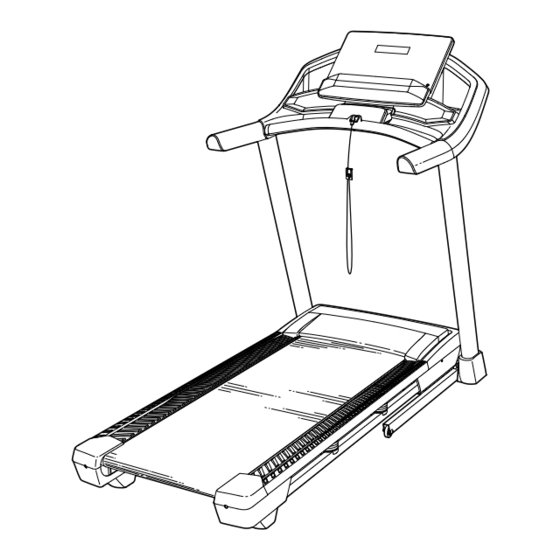
Page 5: Before You Begin
BEFORE YOU BEGIN Thank you for selecting the new PROFORM reading this manual, please see the front cover of this ® TRAINER 8.0 treadmill. The TRAINER 8.0 treadmill manual. To help us assist you, note the product model provides an impressive selection of features designed number and serial number before contacting us. -
Page 6: Part Identification Chart
PART IDENTIFICATION CHART Use the drawings below to identify small parts used for assembly. The number in parentheses below each draw- ing is the key number of the part, from the PART LIST near the end of this manual. The number following the key number is the quantity used for assembly. -
Page 7: Assembly
ASSEMBLY • Assembly requires two persons. • Left parts are marked “L” or “Left” and right parts are marked “R” or “Right.” • Place all parts in a cleared area and remove the packing materials. Do not dispose of the packing •... - Page 8 2. Make sure that the power cord is unplugged. Remove the tie securing the Upright Wire (88) to the front of the Base (97). Next, identify the Right Upright (86). Have a second person hold the Right Upright near the Base (97).
- Page 9 4. Hold the Right Upright (86) against the Base (97). Make sure not to pinch the Upright Wire (88). Insert two 3/8" x 2 3/8" Screws (3) with two 3/8" Star Washers (11) into the top of the bracket on the Right Upright (86).
- Page 10 6. Identify the Left and Right Handrails (80, 81). Attach the Right Handrail (81) to the Right Upright (86) with two 5/16" x 2 1/4" Screws (7) and two 5/16" Star Washers (12) in the location shown; start both Screws, and then tighten them.
- Page 11 8. With the help of a second person, hold the con- sole assembly (F) near the Right Upright (86). Next, insert the Upright Wire (88) through the indicated looped tie (G). Connect the Upright Wire (88) to the wire (H) from the console assembly (F).
- Page 12 10. IMPORTANT: To avoid damaging the Crossbar (87), do not use power tools and do not overtighten the #10 x 3/4" Screws (6). Attach the Crossbar (87) to the Handrails (80, 81) with four #10 x 3/4" Screws (6) and four 1/4"...
- Page 13 12. Note: If the treadmill is assembled on a smooth surface, it may roll forward during this step. Raise the Frame (60) to the upright position. IMPORTANT: Do not raise the Frame past the vertical position. Have a second person hold the Frame until step 14 is completed.
- Page 14 14. Remove the 5/16" Nut (39) and the 5/16" x 2 1/4" Bolt (117) from the bracket on the Latch Crossbar (48). 39 L Align the upper end of the Storage Latch (84) with the bracket on the Latch Crossbar (48), and insert the 5/16"...
-
Page 15: How To Use The Treadmill
HOW TO USE THE TREADMILL HOW TO PLUG IN THE POWER CORD Follow the steps below to plug in the power cord. This product must be earthed. If it should malfunc- 1. Plug the indicated end of the power cord (A) into the tion or break down, earthing provides a path of least socket (B) on the treadmill. - Page 16 CONSOLE DIAGRAM FEATURES OF THE CONSOLE To turn on the power, see page 17. To use the man- ual mode, see page 17. To use an onboard workout, see page 19. To use an iFit workout, see page 20. The treadmill console offers a selection of features designed to make your workouts more effective and To connect a heart rate monitor to the console, see enjoyable.
- Page 17 HOW TO TURN ON THE POWER HOW TO USE THE MANUAL MODE IMPORTANT: If the treadmill has been exposed to 1. Insert the key into the console. cold temperatures, allow it to warm to room tem- perature before you turn on the power. If you do See HOW TO TURN ON THE POWER at the left.
- Page 18 5. Follow your progress with the display. To manually advance the scan cycle, press the Scan button repeatedly. The display can show the following workout To turn off the scan mode, press the Display information: button; the scan indicator and the word SCAN will Calories (CALS)—The approximate number of turn off.
- Page 19 HOW TO USE AN ONBOARD WORKOUT The workout will continue in this way until the last segment ends. The walking belt will then 1. Insert the key into the console. slow to a stop. See HOW TO TURN ON THE POWER on page 17. If the speed or incline setting for the current seg- ment is too high or too low, you can manually over- 2.
- Page 20 HOW TO USE AN IFIT WORKOUT 4. Select an iFit workout. The console offers access to a large and varied library In the iFit app, touch the buttons at the bottom of of iFit workouts when you download the iFit app to your the screen to select either the main menu (Home smart device and connect it to the console.
- Page 21 HOW TO CONNECT A HEART RATE MONITOR TO To pause the workout, simply touch the screen or press the Stop button. To continue the workout, THE CONSOLE press the play icon on the screen, or press the Start button. The console is compatible with Bluetooth Smart heart rate monitors.
- Page 22 THE SETTINGS MODE Unit of Measurement—The currently selected unit of measurement will appear in the display. The 1. Select the settings mode. console can show speed and distance in standard or metric units of measurement. To change the unit To select the settings mode, press of measurement, press the Speed increase button the gear button (K).
- Page 23 Demo Mode—The currently selected demo mode THE OPTIONAL HEART RATE MONITOR option will appear in the display. The console features a demo mode, designed to be used if the Whether your treadmill is displayed in a store. If the demo mode goal is to is turned on, the console will not turn off and the burn fat or to...
-
Page 24: How To Fold And Move The Treadmill
HOW TO FOLD AND MOVE THE TREADMILL HOW TO FOLD THE TREADMILL HOW TO MOVE THE TREADMILL To avoid damaging the treadmill, adjust the incline Before moving the treadmill, fold it as described at the to zero before you fold the treadmill. Then, remove left. -
Page 25: Maintenance And Troubleshooting
MAINTENANCE AND TROUBLESHOOTING MAINTENANCE SYMPTOM: The power turns off during use Regular maintenance is important for optimal per- a. Check the power switch (see drawing c at the left). formance and to reduce wear. Inspect and properly If the switch has tripped, wait for five minutes and tighten all parts each time the treadmill is used. - Page 26 SYMPTOM: The displays of the console do not SYMPTOM: The walking belt slows when walked on function properly a. If an extension cord is needed, use only a 3-conduc- a. Remove the key from the console and UNPLUG tor, 14-gauge (2 mm ) cord that is no longer than THE POWER CORD.
- Page 27 SYMPTOM: The walking belt is not centered SYMPTOM: The walking belt slips when walked on between the foot rails a. First, remove the key and UNPLUG THE POWER a. IMPORTANT: If the walking belt rubs against CORD. Using the hex key, turn both idler roller the foot rails (D), the walking belt may become screws clockwise, 1/4 of a turn.
-
Page 28: Exercise Guidelines
EXERCISE GUIDELINES Aerobic Exercise—If your goal is to strengthen your WARNING: cardiovascular system, you must perform aerobic Before beginning this exercise, which is activity that requires large amounts or any exercise program, consult your physi- of oxygen for prolonged periods of time. For aerobic cian. - Page 29 SUGGESTED STRETCHES The correct form for several basic stretches is shown at the right. Move slowly as you stretch —never bounce. 1. Toe Touch Stretch Stand with your knees bent slightly and slowly bend forward from your hips. Allow your back and shoulders to relax as you reach down toward your toes as far as possible.
-
Page 30: Part List
PART LIST Model No. PFTL59721-INT.0 R0621A Key No. Qty. Description Key No. Qty. Description 3/8" x 1 1/4" Screw Rubber Cushion 3/8" x 1 3/4" Screw 3/8" Pin 3/8" x 2 3/8" Screw Drive Roller/Pulley #8 x 3/4" Screw Controller Clamp #8 x 1/2"... - Page 31 Key No. Qty. Description Key No. Qty. Description Console Frame Clamp Console Ground Wire M4 Nut Console Clamp M4 x 10mm Bolt Key/Clip Filter Console Motor Bushing Console Cable Tie 5/16" x 1 3/4" Bolt Wheel 5/16" x 2 1/4" Bolt 9/32"...
-
Page 32: Exploded Drawing
EXPLODED DRAWING A Model No. PFTL59721-INT.0 R0621A... - Page 33 EXPLODED DRAWING B Model No. PFTL59721-INT.0 R0621A...
- Page 34 EXPLODED DRAWING C Model No. PFTL59721-INT.0 R0621A 2 11 11 1...
- Page 35 EXPLODED DRAWING D Model No. PFTL59721-INT.0 R0621A...
-
Page 36: Ordering Replacement Parts
ORDERING REPLACEMENT PARTS To order replacement parts, please see the front cover of this manual. To help us assist you, be prepared to provide the following information when contacting us: • the model number and serial number of the product (see the front cover of this manual) •...
Need help?
Do you have a question about the PFTL59721-INT.0 and is the answer not in the manual?
Questions and answers
My incline doesn’t always work with the iFit program. There are times it will not incline at all
The incline on the Pro-Form PFTL59721-INT.0 may not work correctly with the iFit program if the incline system is not calibrated. Calibration is needed for proper incline function and can be done by pressing the Incline increase or decrease button, which causes the treadmill to rise to the maximum incline and return to the minimum level. If the incline system is not functioning properly, this calibration step may resolve the issue.
This answer is automatically generated
My treadmill won't stay on
The Pro-Form treadmill PFTL59721-INT.0 may not stay on because:
- The power switch may have tripped. You should wait five minutes and then press the switch back in.
- The power cord may not be plugged into a properly earthed outlet. If it is plugged in, unplug it, wait five minutes, and then plug it back in.
- The key may not be properly inserted into the console. Remove and reinsert the key.
If the treadmill still does not stay on after these steps, further troubleshooting or service may be needed.
This answer is automatically generated