
Subscribe to Our Youtube Channel
Related Manuals for MCZ BOXTHERM 70 PELLET


Summary of Contents for MCZ BOXTHERM 70 PELLET
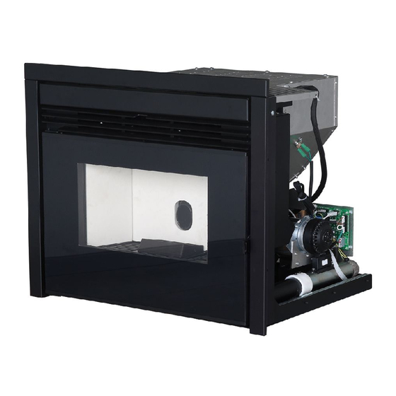
- Page 1 USE AND INSTALLATION MANUAL INSERT BOXTHERM 70 PELLET Translation of original instructions...
- Page 2 TABLE OF CONTENTS TABLE OF CONTENTS ....................II INTRODUCTION ......................1 1-WARNINGS AND WARRANTY CONDITIONS ..............2 2-INSTALLATION ......................8 3-DRAWINGS AND TECHNICAL FEATURES ..............17 4-UNPACKING ......................19 5-ASSEMBLY ......................20 6-FIRST START-UP ....................26 7-LOADING THE PELLETS ...................27 8-LCD REMOTE CONTROL ...................28 9-EMERGENCY PANEL ....................33 10-SAFETY DEVICES AND ALARMS ................37 11-RECOMMENDATIONS FOR SAFE USE ...............41 12-MAINTENANCE AND CLEANING................42...
-
Page 3: Introduction
REVISIONS TO THE PUBLICATION The content of this manual is strictly technical and the property of MCZ Group Spa. No part of this manual may be translated into other languages, adapted or reproduced, even in part, in other mechanical or electronic forms, photocopies, recordings or other, without the prior written authorisation from MCZ Group Spa. -
Page 4: Warnings And Warranty Conditions
1-WARNINGS AND WARRANTY CONDITIONS SAFETY PRECAUTIONS • Installation, electrical connection, function test and maintenance must only be carried out by authorised and qualified personnel. • Install the product in accordance with all local and national legislation and regulations in force in the region or state. •... - Page 5 1-WARNINGS AND WARRANTY CONDITIONS • Do not put linen on the product to dry. Any drying racks or similar objects must be kept at a safe distance from the product. Fire hazard. • All liability for improper use of the product is entirely borne by the user and relieves the Manufacturer from any civil and criminal liability.
- Page 6 1-WARNINGS AND WARRANTY CONDITIONS exposed to weathering. • It is recommended not to remove the feet that support the product in order to guarantee adequate insulation, especially if the flooring is made of flammable materials. • In the event of a malfunction with the ignition system, do not force it to light by using flammable materials.
- Page 7 1-WARNINGS AND WARRANTY CONDITIONS • INFORMATION: Please contact the retailer or qualified personnel authorised by the company to resolve a problem. • You must only use the fuel specified by the manufacturer. • When the product is switched on for the first time it is normal for it to emit smoke due to the paint heating for the first time. Therefore make sure the room in which it is installed is well ventilated.
- Page 8 1-WARNINGS AND WARRANTY CONDITIONS EXCLUSIONS The guarantee does not cover malfunctions and/or damage to the appliance that arise due to the following causes: • Damage caused during transportation or relocation • all parts that develop faults due to negligence or improper use, incorrect maintenance, installation that does not comply with the manufacturer’s instructions (always refer to the installation and use manual provided with the appliance) •...
- Page 9 1-WARNINGS AND WARRANTY CONDITIONS SPARE PARTS In the event of a malfunction, consult the retailer who will forward the call to the Technical Assistance Service. Use only original spare parts. The retailer or service centre can provide all necessary information regarding spare parts. We do not recommend waiting for the parts to be worn before having them replaced.
-
Page 10: Installation
2-INSTALLATION The instructions in this chapter refer explicitly to the Italian installation regulation UNI 10683. In any case, always observe the domestic regulations in force. PELLETS Wood pellets are manufactured by hot-extruding compressed sawdust which is produced during the working of natural dried wood. The compactness of the material is guaranteed by the lignin contained in the wood itself and allows pellets to be produced without glue or binders. - Page 11 If particularly delicate objects are present, such as furniture, curtains or sofas, increase the stove clearance accordingly. If the floor is made of wood, it is recommended to fit a floor protection sheet in compliance with the Standards in force in the country of installation. BOXTHERM 70 PELLET Non-flammable walls Flammable walls...
- Page 12 2-INSTALLATION FOREWORD This chapter on the Smoke Flue has been produced in reference to the prescriptions of European regulations (EN13384 - EN1443 - EN1856 - EN1457). The chapter provides indications for installing an efficient and correct smoke flue but is under no circumstances to substitute the regulations in force, which the qualified technician must be in possession of.
- Page 13 2-INSTALLATION TECHNICAL CHARACTERISTICS Have the efficiency of the flue checked by an authorised technician. The flue must be sealed against flue gasses, in a vertical direction without narrowing, be made with materials impermeable to smoke, condensation, thermally insulated and suitable to resist normal mechanical stress over time (we recommend fireplaces made of A/316 or refractory material with insulated round section double chamber).
- Page 14 2-INSTALLATION ROOF AT 60° ROOF AT 45° 45° 60° A = MIN. 2.60 metres A = MIN. 2.00 metres FIGURE 5 FIGURE 6 B = DISTANCE > 1.20 metres B = DISTANCE > 1.30 metres C = DISTANCE < 1.20 metres C = DISTANCE <...
- Page 15 2-INSTALLATION MAINTENANCE The flue must be kept clean, since the deposit of soot or unburned oils reduces the cross-section reducing the draft and thus compromising the efficient functioning of the heater and, if large build-ups accumulate, can catch fire. The flue and chimneypot must be cleaned and checked by a qualified chimney sweep at least once a year.
- Page 16 2-INSTALLATION EXTERNAL AIR INLET It is mandatory to provide an adequate external air intake that supplies the combustion air required for the product to work properly. The flow of air between the outside and the installation room may be direct, through an inlet in an external wall of the room; or indirect, via air intake from adjoining rooms and connecting permanently with the installation room (see Figure 9 b).
- Page 17 2-INSTALLATION DISTANCE (metres) The air inlet must be at a distance of: 1.5 m UNDER Windows, doors, smoke outlets, cavities, ..1.5 m HORIZONTALLY Windows, doors, smoke outlets, cavities, ..0.3 m ABOVE Windows, doors, smoke outlets, cavities, ..1.5 m AWAY from smoke outlet CONNECTION TO FLUE...
- Page 18 2-INSTALLATION EXAMPLES OF CORRECT INSTALLATION 1. Installation of Ø150mm flue with hole for the passage of the tube increased by: minimum 100 mm around the tube if next to non flammable parts such as cement, brick, etc.; or minimum 300 mm around the tube (or as prescribed by data tags) if next to flammable parts such as wood etc.
-
Page 19: Drawings And Technical Features
3-DRAWINGS AND TECHNICAL FEATURES DRAWINGS AND CHARACTERISTICS BOXTHERM 70 PELLET DIMENSIONS (in cm) Technical Dept. - All rights reserved - Reproduction is prohibited... - Page 20 3-DRAWINGS AND TECHNICAL FEATURES TECHNICAL CHARACTERISTICS BOXTHERM 70 PELLET Nominal output power: 8,8 kw (7568 kcal/h) Minimum output power: 2,6 kw (2236 kcal/h) Efficiency at Max 92,7% Efficiency at Min 95,9% Temperature of exhaust smoke at Max 150 °C Temperature of exhaust smoke at Min 70 °C...
-
Page 21: Unpacking
4-UNPACKING PREPARATION AND UNPACKING The product is supplied in a single package. Open the package, remove the product from the pallet and set it in the pre-selected place, making sure this complies with the requirements. The two brackets must be removed in order to remove the product from pallet, by loosening the two flanged nuts and the two screws. The appliance must always remain in a vertical position and handled solely with a cart. -
Page 22: Assembly
5-ASSEMBLY COMBUSTION AIR (2) During operation a certain amount of air is drawn from the room in which the product is installed and this air must be supplemented through an external air inlet. The combustion air in this product is autonomously drawn directly from the front grille, however, the user can have the air drawn from outside by removing the clamp on the pipe and connecting it directly to outside. - Page 23 5-ASSEMBLY FASTENING TO THE BASE OF THE INSERT It is mandatory to anchor the product to a support as the authorised technician can remove the combustion chamber from its seat by means of two extendable guides while performing the annual maintenance. Fasten the insert as follows: •...
- Page 24 5-ASSEMBLY The product can be installed at the desired height by constructing a suitable platform. This support must be made of non-flammable material. The company declines all liability for any damage to objects and persons if the above-mentioned precautions are not complied with.
- Page 25 5-ASSEMBLY HOOD VENTILATION GRILLES FOR NEW CLADDING It is mandatory to install the hood ventilation grilles of the manufacturer or grilles that can guarantee the same functions and the same air passage section. The company cannot be held liable for any damage caused to the structure or the electrical components if this precaution is not complied with.
- Page 26 5-ASSEMBLY SETTING UP THE CLADDING The product must be fully tested before the cladding is applied. The company cannot be held liable for any damage to the cladding should operating anomalies arise, which were not verified before the cladding was applied to the product. IT IS MANDATORY to check the tightness of all the pipes through which smoke passes (smoke fitting, gaskets and flue coupling) before setting up the cladding.
- Page 27 5-ASSEMBLY ASSEMBLING THE COMPENSATION FRAME Once the cladding and/or the plasterboard is set up, fit the previously removed compensation frame. This frame intends to finish and cover the gap between the metal structure of the product and the cladding. The frame is assembled by simply opening the door of the product, fitting in the frame as shown in the figure and fastening it to the lateral columns of the structure, inside the door profile, with the four screws supplied.
-
Page 28: First Start-Up
6-FIRST START-UP BEFORE START-UP GENERAL PRECAUTIONS Remove all components that could burn from the firebox and the glass (instructions, various adhesive labels and any polystyrene). Check that the brazier is positioned correctly and rests properly on the base. After a long period of inactivity, remove any pellets left in the hopper (using a vacuum cleaner with a long pipe), as they could have absorbed moisture, thereby altering their original characteristics and no longer being suitable for combustion. -
Page 29: Loading The Pellets
7-LOADING THE PELLETS It is extremely important to make sure the product is not immediately overheated and the temperature is increased gradually starting from the low power. This will prevent damaging the welds and the steel structure. DO NOT EXPECT HEATING EFFICIENCY IMMEDIATELY!!! LOADING THE PELLETS Fuel is loaded from the front tray above the door. -
Page 30: Lcd Remote Control
8-LCD REMOTE CONTROL When the appliance is running and when it is turned off, most of the stove surfaces are very hot (door, handle, glass, smoke GENERAL SPECIFICATIONS OF outlet pipes, etc.). Therefore it is recommended to avoid coming into contact with these parts. THE LCD REMOTE CONTROL The remote control works at a transmission frequency of 434.5 MHz. -
Page 31: Remote Control Operation
8-LCD REMOTE CONTROL REMOTE CONTROL OPERATION GENERAL RULES Press key A for 1” to switch the product on and off. All changes are made with keys C. Key E is used to confirm the changes. Key B is used to select the product operating mode. - Page 32 8-LCD REMOTE CONTROL TIMER MODE (TIMER) Select this operating mode to switch the product on and off automatically, according to 6 customised time bands (P1 – P6). The following can be set for each time band: • Start-up time. • Shutdown time.
- Page 33 8-LCD REMOTE CONTROL VARIOUS SETTINGS ROOM VENTILATION The room ventilation can be adjusted as desired in all 4 operating modes described earlier on. Simply follow the steps below: press key D on the initial display to access the VENTILATION setting. Then press key C to set the desired ventilation by selecting one of the 5 levels available.
- Page 34 8-LCD REMOTE CONTROL TIMER SETTINGS DISPLAYING THE TIMER TIME BANDS Simply press key D for 2” to display the time bands in TIMER mode. The 6 time bands can be scrolled through with key C, thereby verifying all the saved settings. Press key D or A to return to the initial display. MO TU WE TH FR SA SU 6:30 8:00...
-
Page 35: Emergency Panel
9-EMERGENCY PANEL EMERGENCY PANEL There is an emergency panel on the product side, designed for any malfunction to be detected and product control if the remote control should malfunction. Three-digit display that indicates a variety of product information besides the identification code of any malfunction. GREEN led that indicates: •... - Page 36 9-EMERGENCY PANEL EMERGENCY PANEL START-UP/SHUTDOWN NIf the remote control is faulty or the batteries are flat, the product can be operated in safe mode via the rear emergency panel. In this configuration, the product can only work in manual mode and one of 3 power levels can be selected. •...
- Page 37 9-EMERGENCY PANEL HOW TO ACCESS THE CONTROL PANEL The control panel is located next to the pellet loading tray and you must proceed as follows to access it. • Open the pellet loading tray. • A compartment is found in the top right part, and use the cold handle (supplied) to pull out the control panel. •...
- Page 38 9-EMERGENCY PANEL FEED SCREW LOADING This function can only be activated when the product is off and allows the pellets to be loaded into the feed screw (loading system). It can be used each time the pellets finish in the feed screw and hopper (see alarm A02). It is useful to prevent failed start-ups (alarm A01) due to the hopper being empty.
-
Page 39: Safety Devices And Alarms
10-SAFETY DEVICES AND ALARMS SAFETY DEVICES The product is supplied with the following safety devices: SMOKE TEMPERATURE PROBE Detects the temperature of the smoke, thereby enabling start-up or stopping the product when the temperature drops below the preset value. PELLET HOPPER SAFETY THERMOSTAT If the temperature exceeds the preset safety value, it immediately stops the product, which must cool down before being restarted. - Page 40 10-SAFETY DEVICES AND ALARMS ALARM ALERTS If an operating anomaly occurs, the product enters the shutdown phase due to an alarm and informs the user regarding the type of fault by means of a 3 digit code that remains displayed on the emergency panel. The alarm is indicated permanently by the relative 3 digit code, a flashing red LED that lights up on the emergency panel and an intermittent buzzer for the first 10 minutes.
- Page 41 10-SAFETY DEVICES AND ALARMS The spark plug is faulty. Contact an authorised service centre to have the component replaced. Pellet supply fault. Contact an authorised service centre to have the component replaced. The remote control has been out of the product Move the remote control within the product reception reception range for over 3 hours (or the batteries range (or change the batteries of the remote control if...
- Page 42 10-SAFETY DEVICES AND ALARMS BLOCKED APPLIANCE The following may cause the product to be mechanically blocked: • The structure overheats (“A03”). • The smoke is overheated (“A04”). • During product operation, air that has not been controlled in the combustion chamber has entered or the flue is clogged. (“A05”). SOLUTIONS: If “A03”...
-
Page 43: Recommendations For Safe Use
11-RECOMMENDATIONS FOR SAFE USE ONLY CORRECT INSTALLATION AND APPROPRIATE MAINTENANCE AND CLEANING OF THE APPLIANCE CAN GUARANTEE CORRECT OPERATION AND SAFE USE OF THE PRODUCT. We would like to inform you that we are aware of cases of malfunctioning of domestic pellet-fuelled heating products, mainly due to incorrect installation and inappropriate maintenance. -
Page 44: Maintenance And Cleaning
12-MAINTENANCE AND CLEANING EXAMPLE OF A CLEAN BRAZIER EXAMPLE OF A DIRTY BRAZIER Only by properly servicing and cleaning the product is it possible to ensure its safety and correct operation. ATTENTION! All the cleaning operations of all parts must be performed with the product completely cold and the plug disconnected. - Page 45 12-MAINTENANCE AND CLEANING CLEANING THE GLASS It is recommended to clean the ceramic glass with a dry brush, or if it is very dirty, spray a little specific detergent and clean with a cloth. ATTENTION! Do not use abrasive products and do not spray the glass spray cleaner on the painted parts or the door gaskets (ceramic fibre cord).
- Page 46 12-MAINTENANCE AND CLEANING A - BRACKET B - SCREW C - BRAZIER D - ASH DRUM E - LATERAL SIDE F - REAR PART...
- Page 47 12-MAINTENANCE AND CLEANING Then remove the upper plate “Q”. Remove it from its seat by lifting it and then tilting it slightly downwards. Scrape the walls of the firebox with a rigid rod or a bottle brush into plate “Q” that has just been removed, for the ash to fall into the lower part where the inspection holes are located (under plates “R”).
- Page 48 12-MAINTENANCE AND CLEANING CLEANING THE SMOKE DUCT AND FITTING When the product is extracted, you can intervene on the smoke fan (1) from the left side for cleaning and maintenance purposes. Clearly, the smoke evacuation fan must be removed for such maintenance to be performed. A gasket (3) is applied on the fan outlet, which guarantees the tightness with the smoke fitting (2).
- Page 49 12-MAINTENANCE AND CLEANING END-OF-SEASON SHUTDOWN At the end of each season, before switching the product off, it is recommended to remove all the pellets from the hopper with a vacuum cleaner that has a long pipe. The product must be disconnected from the mains when it is not used. CHECKING THE INTERNAL COMPONENTS ATTENTION! The internal electromechanical components must only be checked by qualified personnel whose technical expertise...
-
Page 50: Problems/Causes/Solutions
13-PROBLEMS/CAUSES/SOLUTIONS ATTENTION: All repairs must only be carried out by a specialised technician, with the product switched off and the plug disconnected. If the product is NOT used as described in this instruction manual, the manufacturer declines all liability for any damage caused to persons and property. - Page 51 13-PROBLEMS/CAUSES/SOLUTIONS ANOMALY POSSIBLE CAUSES SOLUTIONS The product works for a few minutes Start-up phase is not completed Repeat start-up and then switches off Temporary power cut Wait for the automatic restart Clogged smoke duct Clean the smoke duct Faulty or malfunctioning temperature probes Check and replace the probes Faulty spark plug Check the spark plug and replace it, if necessary...
- Page 52 13-PROBLEMS/CAUSES/SOLUTIONS ANOMALY POSSIBLE CAUSES SOLUTIONS The product always runs at maximum The room thermostat is in the maximum Set the thermostat temperature again. power when in automatic mode position Faulty temperature probe Check the panel and replace it, if necessary Faulty or malfunctioning control panel Check the probe and replace it, if necessary Thermostat is set to minimum...
-
Page 53: Wiring Diagrams
14-WIRING DIAGRAMS MOTHERBOARD WIRING KEY EMERGENCY PANEL GEAR MOTOR SMOKE PROBE CONTACT THERMOSTAT MODEM CONNECTION 10. AIR FAN SWITCH 11. SMOKE EXPULSION FAN REV CONTROL SPARK PLUG 12. AIR DOOR PROBE SMOKE EXPULSION FAN N.B. The wiring of the individual components is fitted with pre-wired connectors of different sizes. Technical Dept. - Page 56 MCZ GROUP S.p.A. Via La Croce n°8 33074 Vigonovo di Fontanafredda (PN) – ITALY Telephone: +39 0434/599599 r.a. Fax: +39 0434/599598 Internet: www.mcz.it e-mail: mcz@mcz.it 8901612300 REV.2 05/07/2017...
Need help?
Do you have a question about the BOXTHERM 70 PELLET and is the answer not in the manual?
Questions and answers