MCZ FLAT Use And Installation Manual
Hide thumbs
Also See for FLAT:
- Use and installation manual (112 pages) ,
- Use and installation manual (60 pages)

Related Manuals for MCZ FLAT


Summary of Contents for MCZ FLAT
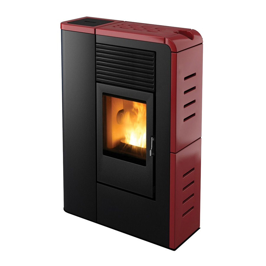
- Page 1 USE AND INSTALLATION MANUAL PELLET STOVE FLAT COMFORT AIR MADE OF CERAMICS FLAIR COMFORT AIR MADE OF STEATITE Translation of original instructions...
-
Page 2: Table Of Contents
TABLE OF CONTENTS TABLE OF CONTENTS ....................II INTRODUCTION ......................1 1-WARNINGS AND WARRANTY CONDITIONS ..............2 2-INSTALLATION INSTRUCT ..................5 3-INSTALLATION AND ASSEMBLY ................13 4-LCD REMOTE CONTROL ...................31 5-EMERGENCY PANEL ....................36 6-SAFETY DEVICES AND ALARMS ................39 7-MAINTENANCE AND CLEANING ................43 8-PROBLEMS/CAUSES/SOLUTIONS ................47 9-WIRING DIAGRAMS ....................50... -
Page 3: Introduction
No part of this manual can be translated into another language and/or altered and/or reproduced, even partially, in another form, by mechanical or electronic means, photocopied, recorded or similar, without prior written approval from MCZ Group Spa. The company reserves the right to make changes to the product at any time without prior notice. The proprietary company reserves its rights according to the law. -
Page 4: 1-Warnings And Warranty Conditions
1-WARNINGS AND WARRANTY CONDITIONS SAFETY PRECAUTIONS • Installation, electrical connection, functional verification and maintenance must only be performed by qualified or authorised personnel. • Install the product in accordance with all the local and national laws and Standards applicable in the relative place, region or country. - Page 5 1-WARNINGS AND WARRANTY CONDITIONS INFORMATION: Please contact the retailer or qualified personnel authorised by the company to resolve a problem. • Only fuel stipulated by the company must be used. • Check and clean the smoke outlet pipes regularly (connection with the chimney). • The product is not a cooking appliance.
- Page 6 1-WARNINGS AND WARRANTY CONDITIONS INTERVENTION REQUEST The company declines all liability if the product and any other accessory is used incorrectly or altered without authorisation. All parts must be replaced with original spare parts. The request must be sent to the retailer who will forward it to the Technical Assistance Department. SPARE PARTS Only original spare parts must be used.
-
Page 7: 2-Installation Instruct
2-INSTALLATION INSTRUCT The requirements in this chapter refer to the regulations of the Italian installation Standard UNI 10683. In any case, always comply with the regulations in force in the country of installation. PELLETS Wood pellets are obtained from compressing sawdust produced during the processing of natural dried wood (without paint). The compactness of the material is guaranteed by the lignin contained in the wood itself and allows pellets to be produced without glue or binders. - Page 8 2-INSTALLATION INSTRUCT PRECAUTIONS REGARDING INSTALLATION IMPORTANT! Product installation and assembly must be carried out by qualified personnel. The product must be installed in a suitable place for it to be regularly opened and routine maintenance to be performed. The environment must be: • Compliant for proper operation.
- Page 9 It is forbidden to place the product in an explosive atmosphere. MINIMUM DISTANCES Room ventilation can only be set towards the rear wall if there is adequate insulated ducting of the hot air flow. FLAT - FLAIR Non-flammable walls Flammable walls...
- Page 10 2-INSTALLATION INSTRUCT CONNECTION OF THE SMOKE EXHAUST DUCT When drilling the hole for the smoke exhaust pipe, the possible presence of flammable materials must be considered. If the hole must be made through a wooden wall or thermolabile material, the INSTALLER MUST first use the relative wall fitting (minimum diam. 13 cm) and adequately insulate the pipe of the product that passes through it, using suitable insulating material (1.3 - 5 cm thick with minimum thermal conductivity 0.07 W/m°K).
- Page 11 2-INSTALLATION INSTRUCT Always use pipes and fittings with appropriate seals that guarantee tightness. It must be possible to inspect all sections of the flue duct and they must be removable for periodic internal cleaning (T-fitting with inspection hole). Position the product considering all the above requirements and instructions. IMPORTANT! The following conditions must be complied with when connecting the appliance to the chimney: • ...
- Page 12 2-INSTALLATION INSTRUCT CONNECTION TO THE EXTERNAL AIR INTAKE It is essential for the room where the product is installed to be adequately ventilated in order to guarantee sufficient air for proper combustion in the appliance. This is possible by means of suitable ventilation openings in the room itself or in an interconnected room through a permanent opening between the rooms (room ventilation is excluded in the case of installation with Oyster technology, where combustion air is ducted directly from outside).
- Page 13 2-INSTALLATION INSTRUCT CONNECTIONS CONNECTION TO THE CHIMNEY CONNECTION TO AN EXTERNAL DUCT CONNECTION TO THE CHIMNEY WITH AN INSULATED OR DOUBLE-WALL PIPE The internal dimensions of the chimney The minimum internal dimensions of the The connection between the product and must not exceed 20x20 cm or 20 cm in external duct must be 10x10 cm or 10 cm the chimney or the smoke duct must not...
- Page 14 2-INSTALLATION INSTRUCT OPERATING PROBLEMS RELATED TO DRAUGHT DEFECTS IN THE CHIMNEY Among all the weather and geographical conditions that affect chimney operation (rain, fog, snow, altitude a.s.l., exposure to sunlight, orientation to the cardinal points, etc.), the wind is certainly the most determinant. In fact, besides the thermal depression caused by the difference in temperature between inside and outside the chimney, there is another type of depression (or overpressure): dynamic pressure caused by the wind.
-
Page 15: 3-Installation And Assembly
3-INSTALLATION AND ASSEMBLY DRAWINGS AND CHARACTERISTICS FLAT COMFORT AIR DIMENSIONS (in mm) Technical Dept. - All rights reserved - Reproduction is prohibited... - Page 16 3-INSTALLATION AND ASSEMBLY FLAIR COMFORT AIR DIMENSIONS (in mm)
- Page 17 3-INSTALLATION AND ASSEMBLY TECHNICAL CHARACTERISTICS FLAT-FLAIR COMFORT AIR Max. overall thermal power 8 kw / 6880 kcal Min. overall thermal power 3,2 kw / 2580 kcal Efficiency at Max 87,8% Efficiency at Min 93,6% Temperature of exhaust smoke at Max 160°C...
- Page 18 3-INSTALLATION AND ASSEMBLY PREPARATION AND UNPACKING The FLAT/FLAIR stove is delivered on a pallet with a number of packages (fig. 2): • The first contains the stove (fig. 1). • The second contains the ceramic or serpentine panels (two sides + two tops).
- Page 19 3-INSTALLATION AND ASSEMBLY REMOVE THE TWO SCREWS FROM THE FOUR BRACKETS REMOVE THE BRACKETS FIGURE 3 - REMOVING THE PACKAGE SCREWS Technical Dept. - All rights reserved - Reproduction is prohibited...
- Page 20 3-INSTALLATION AND ASSEMBLY Position the product without its cladding and connect it to the chimney. Once the connections are complete, assemble the cladding (ceramic or serpentine sides). If the product must be connected to an exhaust pipe that goes through the rear wall (to enter the chimney), make sure not to force it in. Adjust the 4 feet (J) to level the stove for the smoke exhaust and the pipe to be coaxial.
- Page 21 3-INSTALLATION AND ASSEMBLY CONNECTION OF THE SMOKE OUTLET PIPE You can choose whether to release the smoke on the rear part or upper part of the product. If you wish to connect the smoke outlet to the upper part, remove the cap with the three screws from under the top. Then insert the pipe until it engages with the smoke fitting.
- Page 22 3-INSTALLATION AND ASSEMBLY If you wish to connect the smoke outlet to the rear part, turn the T-fitting towards the rear of the product. Then connect the pipes. TURN THE T-FITTING FOR THE REAR SMOKE OUTLET.
- Page 23 3-INSTALLATION AND ASSEMBLY CONNECTING THE HOT AIR DUCTING The standard product has two fans installed for air distribution with the nozzle directed towards the front part of the stove. Therefore, the first important thing to decide is whether to channel the air or not. In line with this, turn the fan (2) for the air to be released towards the rear part.
- Page 24 3-INSTALLATION AND ASSEMBLY FAN 2 TURNED FOR REAR AIR. FAN 2 ORIGINAL POS. The air can be channelled by fastening a flexible pipe on the rear part of the product with a clamp, in line with the hole on the upper part. The air can now be released from the front and rear, only from the front or only from the rear.
- Page 25 3-INSTALLATION AND ASSEMBLY It is recommended to insulate the entire length of the pipe in order to reduce dispersion and increase heat output in the room. A - STOVE B - HOT AIR OUTLET PIPE C - INSULATION WALL D - INSULATION If the wall that is to be drilled through is made of flammable material, the INSTALLER MUST adequately insulate the pipe of the stove that passes through it, using suitable insulating material (1.3 - 5 cm thick with min.
- Page 26 3-INSTALLATION AND ASSEMBLY ASSEMBLING THE CLADDING ASSEMBLING THE SIDE PANELS The product is supplied with the ceramic or serpentine panels packaged separately, therefore unpack all the parts before proceeding with the assembly. The ceramic and serpentine stone panels are assembled in the same way. Follow the sequence below to assemble the panels: •...
- Page 27 3-INSTALLATION AND ASSEMBLY Panel B can be fastened by following the procedures implemented to assemble panel A. The pins on the lower part of the panel - • pos. d - must enter the holes in the structure, whereas two screws on the upper part of the panel, block it to the structure - pos. f. Panel B rests on the two adjustable screws “e”.
- Page 28 3-INSTALLATION AND ASSEMBLY ASSEMBLING THE TOP The top does not require particular fastening as it is only placed on the structure of the product in line with the relative vibration dampers. Therefore, once panels A and B are fitted, parts C and D can be assembled with the hopper cover E.
- Page 29 ATTENTION! The door must be closed properly for the product to work correctly. The door of the Flat/Flair stove is opened by inserting the cold handle on the opening hook of the door, lifting and pulling. OPENING THE DOOR. ELECTRICAL CONNECTION First connect the power cable to the side of the stove and then to a wall socket.
- Page 30 3-INSTALLATION AND ASSEMBLY BEFORE START-UP GENERAL PRECAUTIONS Remove all components that could burn from the brazier and the glass (manual, various adhesive labels and any polystyrene). Check that the brazier is positioned correctly and rests properly on the base. After a long period of inactivity, remove any pellets left in the hopper (using a vacuum cleaner with a long pipe), as they could have absorbed moisture, thereby altering their original characteristics and no longer being suitable for combustion.
- Page 31 3-INSTALLATION AND ASSEMBLY It is good practice to guarantee effective ventilation in the room during the initial start-up, as the stove will emit some smoke and smell of paint. Do not stand close to the stove and air the room. The smoke and smell of paint will disappear after about an hour of operation, however, remember they are not harmful in any case.
- Page 32 3-INSTALLATION AND ASSEMBLY LOADING THE PELLETS Fuel is loaded by lifting the cover on the upper part of the product. Slowly pour the pellets into the hopper. Be careful as the cover could become very hot. LIFT THE COVER. INSERT THE PELLETS. No other type of fuel other then pellets, in compliance with above-mentioned specifications, is to be inserted into the hopper.
-
Page 33: 4-Lcd Remote Control
The time must be set when the remote control is switched on. The remote control has a special icon on the display to indicate when the batteries are almost flat. If the flat battery icon appears, the batteries are almost flat and the remote control is about to go off. - Page 34 4-LCD REMOTE CONTROL LCD REMOTE CONTROL OPERATION GENERAL RULES Press key A for 1” to switch the product on and off. All changes are made with keys C. Key E is used to confirm the changes. Key B is used to select the product operating mode.
- Page 35 4-LCD REMOTE CONTROL TIMER MODE (TIMER) Select this operating mode to switch the product on and off automatically, according to 6 customised time bands (P1 – P6). The following can be set for each time band: • Start-up time. • Shutdown time.
- Page 36 4-LCD REMOTE CONTROL VARIOUS SETTINGS ROOM VENTILATION The room ventilation can be adjusted as desired in all 4 operating modes described earlier on. Simply follow the steps below: press key D on the initial display to access the VENTILATION setting. Then press key C to set the desired ventilation by selecting one of the 5 levels available.
- Page 37 4-LCD REMOTE CONTROL TIMER SETTINGS DISPLAY THE TIMER TIME BANDS Simply press key D for 2” to display the time bands in TIMER mode. The 6 time bands can be scrolled through with key C, thereby verifying all the saved settings. Press key D or A to return to the initial display. MO TU WE TH FR SA SU 6:30 8:00...
-
Page 38: 5-Emergency Panel
5-EMERGENCY PANEL EMERGENCY PANEL There is an emergency panel on the product side, designed for any malfunction to be detected and product control if the remote control should malfunction. Three-digit display that indicates a variety of product information besides the identification code of any malfunction. GREEN LED that indicates: •... - Page 39 EMERGENCY PANEL START-UP/SHUTDOWN If the remote control is faulty or the batteries are flat, the product can be operated in safe mode via the rear emergency panel. In this configuration, the product can only work in manual mode and one of 3 power levels can be selected.
- Page 40 5-EMERGENCY PANEL LOAD THE FEED SCREW This function can only be activated when the stove is off and allows the pellets to be loaded into the feed screw (loading system). It can be used each time the pellets finish in the feed screw and hopper (see alarm A02). It is useful to prevent failed start-ups (alarm A01) due to the hopper being empty.
-
Page 41: 6-Safety Devices And Alarms
6-SAFETY DEVICES AND ALARMS SAFETY DEVICES The product is supplied with the following safety devices: SMOKE TEMPERATURE PROBE Detects the temperature of the smoke, thereby enabling start-up or stopping the product when the temperature drops below the preset value. PELLET HOPPER SAFETY THERMOSTAT If the temperature exceeds the preset safety value, it immediately stops the product, which must cool down before being restarted. - Page 42 6-SAFETY DEVICES AND ALARMS ALARM ALERTS If an operating anomaly occurs, the product enters the shutdown phase due to an alarm and informs the user regarding the type of fault by means of a 3 digit code that remains displayed on the emergency panel. The alarm is indicated permanently by the relative 3 digit code, a flashing red LED that lights up on the emergency panel and an intermittent buzzer for the first 10 minutes.
- Page 43 3 hours (or the batteries range (or change the batteries of the remote control if are flat). they are flat). The alarm alerts will disappear as soon NOTE: the appliance does not enter the as the appliance receives a new signal from the remote shutdown phase due to an alarm only in such a control.
- Page 44 6-SAFETY DEVICES AND ALARMS BLOCKED PRODUCT The following may cause the product to be mechanically blocked: • The structure overheats (“A03”). • The smoke is overheated (“A04”). • During product operation, air that has not been controlled in the combustion chamber has entered or the chimney is clogged (“A05”). SOLUTIONS: If “A03”...
-
Page 45: 7-Maintenance And Cleaning
7-MAINTENANCE AND CLEANING EXAMPLE OF A CLEAN BRAZIER EXAMPLE OF A DIRTY BRAZIER ATTENTION! All the cleaning operations of all parts must be performed with a completely cold product and the plug disconnected. The product requires little maintenance if used with certified good quality pellets. DAILY OR WEEKLY CLEANING PERFORMED BY THE USER BEFORE EACH START-UP Clean the ash and any deposits in the brazier that could clog the air passage holes. - Page 46 7-MAINTENANCE AND CLEANING CLEANING THE GLASS It is recommended to clean the ceramic glass with a dry brush, or if it is very dirty, spray a little specific detergent and clean with a cloth. ATTENTION! Do not use abrasive products and do not spray the glass spray cleaner on the painted parts or the door gaskets (ceramic fibre cord).
- Page 47 The company recommends contacting an authorised service centre for end-of-season maintenance and cleaning as the above-mentioned operations will be performed together with a general inspection of the components. CLEANING THE FLAT STOVE EXCHANGER CLEANING THE FLAT STOVE T-FITTING Technical Dept. - All rights reserved - Reproduction is prohibited...
- Page 48 7-MAINTENANCE AND CLEANING END-OF-SEASON SHUTDOWN At the end of each season, before switching the product off, it is recommended to remove all the pellets from the hopper with a vacuum cleaner that has a long pipe. The appliance must be disconnected from the mains when it is not used. It is recommended to remove the power cable for additional safety, especially in the presence of children.
-
Page 49: 8-Problems/Causes/Solutions
8-PROBLEMS/CAUSES/SOLUTIONS ATTENTION! All repairs must only be carried out by a specialised technician, with the product switched off and the plug disconnected. If the product is NOT used as described in this manual, the manufacturer declines all liability for any damage caused to persons and property. - Page 50 Check the probe and replace it, if necessary. control probe. Faulty fan. Check the fan and replace it, if necessary. The remote control does not work. The remote control battery is flat. Replace the batteries. Faulty remote control. Replace the remote control.
- Page 51 8-PROBLEMS/CAUSES/SOLUTIONS The product always runs at maximum The room thermostat is in the maximum Set the thermostat temperature. power when in automatic mode. position. Faulty temperature probe. Check the probe and replace it, if necessary. Faulty or malfunctioning control panel. Check the panel and replace it, if necessary.
-
Page 52: 9-Wiring Diagrams
9-WIRING DIAGRAMS MOTHERBOARD WIRING KEY EMERGENCY PANEL GEAR MOTOR SMOKE PROBE CONTACT THERMOSTAT MODEM CONNECTION 10. AIR FAN SWITCH 11. SMOKE EXPULSION FAN REV CONTROL SPARK PLUG 12. AIR DOOR PROBE SMOKE EXPULSION FAN N.B. The wiring of the individual components is fitted with pre-wired connectors of different sizes. - Page 56 MCZ GROUP S.p.A. Via La Croce n°8 33074 Vigonovo di Fontanafredda (PN) – ITALY Telephone: 0434/599599 r.a. Fax: 0434/599598 Internet: www.mcz.it e-mail: mcz@mcz.it For further technical information regarding installation or operation please contact the TECHNICAL ASSISTANCE – AFTER-SALES DEPARTMENT Monday to Friday 8.00 to 12.00 and 14.00 to 18.00...
Need help?
Do you have a question about the FLAT and is the answer not in the manual?
Questions and answers