Table of Contents
Advertisement
Advertisement
Table of Contents

Subscribe to Our Youtube Channel
Related Manuals for MCZ CUTE


Summary of Contents for MCZ CUTE
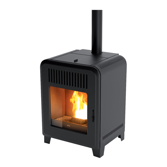
- Page 1 INSTALLATION GUIDE PELLET STOVE CUTE/THEMA AIR Instructions in English...
-
Page 2: Table Of Contents
TABLE OF CONTENTS TABLE OF CONTENTS ....................II INTRODUCTION ......................1 1-WARNINGS AND WARRANTY CONDITIONS ..............2 2-FUEL ........................6 3-INSTALLATION ......................7 4-FLUE ........................8 5-DRAWINGS AND TECHNICAL FEATURES ..............15 6-INSTALLATION AND ASSEMBLY ................18 7-REMOTE CONTROL MAX ..................25 8-EMERGENCY PANEL ....................31 9-OPERATION ......................33 10-SAFETY DEVICES ....................36 11-ALARMS ......................37 12-CLEANING ......................40 13-FAULTS/CAUSES/SOLUTIONS .................46... -
Page 3: Introduction
REVISIONS TO THE PUBLICATION The content of this manual is strictly technical and the property of MCZ Group Spa. No part of this manual may be translated into other languages and/or adapted and/or reproduced, even in part, in other mechanical or electronic forms, photocopies, recordings or other, without the prior written authorisation from MCZ Group Spa. -
Page 4: Warnings And Warranty Conditions
1-WARNINGS AND WARRANTY CONDITIONS SAFETY PRECAUTIONS • Installation, electrical connection, function test and maintenance must only be carried out by authorised and qualified personnel. • Install the product in accordance with all local and national legislation and regulations in force in the region or state. • Only use the fuel recommended by the manufacturer. - Page 5 1-WARNINGS AND WARRANTY CONDITIONS INFORMATION: Please contact the retailer or qualified personnel authorised by the company to resolve a problem. • You must only use the fuel specified by the manufacturer. • When the product is switched on for the first time it is normal for it to emit smoke due to the paint overheating for the first time. Therefore make sure the room in which it is installed is well ventilated.
- Page 6 1-WARNINGS AND WARRANTY CONDITIONS EXCLUSIONS The guarantee does not cover malfunctions and/or damage to the appliance that arise due to the following causes: • Damage caused during transportation and/or handling • all parts that develop faults due to negligence or improper use, incorrect maintenance, installation that does not comply with the manufacturer’s instructions (always refer to the installation and use manual provided with the appliance) •...
- Page 7 1-WARNINGS AND WARRANTY CONDITIONS SPARE PARTS In the event of a malfunction, consult the retailer who will forward the call to the Technical Assistance Service. Only use original spare parts. The retailer or service centre can provide all necessary information regarding spare parts. We do not recommend waiting for the parts to get worn out before having them replaced.
-
Page 8: Fuel
2-FUEL The instructions in this chapter refer explicitly to the Italian installation regulation UNI 10683. In any case, always observe the regulations in force in the country of installation. PELLETS Wood pellets are manufactured by hot-extruding compressed sawdust which is produced during the working of natural dried wood. The compactness of the material is guaranteed by the lignin contained in the wood itself and allows pellets to be produced without glue or binders. -
Page 9: Installation
If the floor is made of wood, it is recommended to fit a floor protection sheet in compliance with the Standards in force in the country of installation. Non-flammable walls Flammable walls CUTE/THEMA A = 5 cm A = 5 cm B = 5 cm B = 5 cm If the floor is made of combustible material, it is recommended to use protection made of non-combustible material (steel, glass...) that... -
Page 10: Flue
4-FLUE FOREWORD The Chimney Flue chapter has been drawn up with reference to the provisions of European Standards (EN13384 - EN1443 - EN1856 - EN1457). The chapter provides instructions for installing a chimney flue efficiently and properly, but under no circumstances is it a substitute of the Standards in force, which the qualified technician must be in possession of. - Page 11 4-FLUE TECHNICAL CHARACTERISTICS Have the efficiency of the flue checked by an authorised technician. The flue must be sealed against flue gasses, in a vertical direction without narrowing, be made with materials impermeable to smoke, condensation, thermally insulated and suitable to resist normal mechanical stress over time (we recommend fireplaces made of A/316 or refractory material with insulated round section double chamber).
- Page 12 4-FLUE ROOF AT 60° ROOF AT 45° 45° 60° A = MIN. 2.60 metres A = MIN. 2.00 metres FIGURE 5 FIGURE 6 B = DISTANCE > 1.20 metres B = DISTANCE > 1.30 metres C = DISTANCE < 1.20 metres C = DISTANCE <...
- Page 13 4-FLUE MAINTENANCE The flue must be kept clean, since the deposit of soot or unburned oils reduces the cross-section reducing the draft and thus compromising the efficient operation of the stove and, if large build-ups accumulate, can catch fire. The flue and chimney must be cleaned and checked by a qualified chimney sweep at least once a year.
- Page 14 4-FLUE EXTERNAL AIR INLET It is mandatory to provide an adequate external air intake that supplies the combustion air required for the product to work properly. The flow of air between the outside and the installation room may be direct, through an inlet in an external wall of the room; or indirect, via air intake from adjoining rooms and connecting permanently with the installation room (see Figure 9 b).
- Page 15 4-FLUE DISTANCE (metres) The air inlet must be at a distance of: 1.5 m UNDER Windows, doors, smoke outlets, cavities, ..1.5 m HORIZONTALLY Windows, doors, smoke outlets, cavities, ..0.3 m ABOVE Windows, doors, smoke outlets, cavities, ..1.5 m AWAY from smoke outlet CONNECTION TO THE FLUE...
- Page 16 4-FLUE EXAMPLES OF CORRECT INSTALLATION 1. Installation of Ø120mm flue with hole for the passage of the pipe increased by: minimum 100mm around the pipe if next to non flammable parts such as cement, brick, etc.; or minimum 300mm around the pipe (or as required by data tags) if next to flammable parts such as wood etc.
-
Page 17: Drawings And Technical Features
5-DRAWINGS AND TECHNICAL FEATURES DRAWINGS AND CHARACTERISTICS CUTE AIR STOVE DIMENSIONS Ø100 Technical Dept. - All rights reserved - Reproduction is prohibited... - Page 18 5-DRAWINGS AND TECHNICAL FEATURES THEMA AIR STOVE DIMENSIONS Ø100...
- Page 19 5-DRAWINGS AND TECHNICAL FEATURES TECHNICAL CHARACTERISTICS CUTE/THEMA Model AIR Nominal output power 8 kW (6880 kcal/h) Minimum output power 2,4 kW (2064 kcal/h) Efficiency at Max 90,5% Efficiency at Min 90,0% Temperature of exhaust smoke at Max 170 °C Temperature of exhaust smoke at Min 100 °C...
-
Page 20: Installation And Assembly
The stove CUTE/THEMA is delivered in a single package. Open the package, remove the two screws “v” which secure the stove brackets to the pallet and then remove the bracket “S” from the stove foot. - Page 21 6-INSTALLATION AND ASSEMBLY Therefore, the end user is responsible for product storage, disposal or possible recycling in compliance with the relative applicable laws in force. Do not store the stove unit or its cladding without their packaging. Position the stove and connect it to the flue pipe. If the stove needs to be connected to an outlet pipe which goes through the rear wall (to connect to the flue), take utmost care to make sure that the joint is not forced.
- Page 22 6-INSTALLATION AND ASSEMBLY DISASSEMBLING THE SIDE CLADDING In the event the side has to be removed, proceed as follows: • Open the door ”P” • Remove the two screws “v” at the front of the stove • Remove the two screws “t” at the back of the stove •...
- Page 23 6-INSTALLATION AND ASSEMBLY ASSEMBLING THE THEMA STOVE CERAMIC/STEATITE Take the front panel (ceramic or steatite) “G” and fit the slots “P”, located at the back of the panel, on the screws “O” on the front of the stove. Then clamp the panel to the stove by tightening the two screws “O” via the holes in the panel “G” itself. Technical Dept.
- Page 24 6-INSTALLATION AND ASSEMBLY MODEM INSTALLATION “M”/WEB-WIFI INTERFACE “N” Install the Modem “M” or the Web-Wi-Fi-Interface “N” using the holes on the back of the product and follow the instructions on the product chosen. USB SOCKET There is a USB socket on the back of the stove, if a software update is required; the ceramic/metal parts do not have to be removed to reach the socket directly in the circuit board (pos.
- Page 25 6-INSTALLATION AND ASSEMBLY LOADING THE PELLETS Fuel is loaded from the upper part of the stove by lifting the door. Pour the pellets in slowly so that it is deposited at the bottom of the hopper. Never remove the protection grid inside the hopper. When loading, do not let the pellet bag come into contact with hot surfaces.
- Page 26 6-INSTALLATION AND ASSEMBLY PRECAUTIONS BEFORE START-UP GENERAL PRECAUTIONS Remove any objects that may burn from the brazier (manual, various adhesive labels or any polystyrene). Check that the brazier is positioned correctly and rests properly on the base. The first start-up may not be successful as the feed screw is empty and does not always manage to load the required amount of pellets in time to light the flame.
-
Page 27: Remote Control Max
7-REMOTE CONTROL MAX GENERAL FEATURES OF THE LCD REMOTE CONTROL The remote control works at a transmission frequency of 434.5 MHz. Power the product with 3 AAA batteries as follows: Remove the battery compartment cover by pressing and lifting according to the arrow Insert the batteries observing the correct polarity (+) and (-) Close the battery compartment cover. - Page 28 7-REMOTE CONTROL MAX REMOTE CONTROL OPERATION General rules By pressing key A for 1” the product is switched on and off. Key C is used to make all changes. Key E is used to confirm the changes. By pressing key B one selects the product operating mode. Via key D one browses the FAN and SLEEP setting. Whichever the mode is, press key A briefly (or leave the keypad idle for 7”) to go back to the initial display.
- Page 29 7-REMOTE CONTROL MAX TIMER Mode (TIMER) Select this operating mode to switch the product on and off automatically, according to 6 customised time slots (P1 – P6). The following can be set for each time slot: • Switch-on time • Switch-off time •...
- Page 30 7-REMOTE CONTROL MAX VARIOUS SETTINGS Room ventilation Room ventilation can be adjusted as desired in all 4 operating modes described above. Simply perform this operation: from the basic display, press key D to access the VENTILATION adjustment mode (figure 6). Then press key C to set the desired ventilation by selecting one of the 5 levels available, independent from the flame level.
- Page 31 7-REMOTE CONTROL MAX SILENT FUNCTION (SF) The SILENT function allows the stove to operate at the minimum power throughout the whole night and, therefore, to turn off the room’s ventilation. This function is only available in AUTO and MAN (mode, not in TIMER mode). Proceed as follows to set it: from the VENTILATION adjustment (by pressing key D), press key D again and you will enter the SLEEP adjustment area.
- Page 32 7-REMOTE CONTROL MAX TIMER settings TIMER time slot display In TIMER mode, to display the time slots simply press key D for 2”. With key C one can scroll the 6 time slots freely, quickly checking the saved settings (figure 8). By pressing key D or A one goes back to the basic display. FIG.8 FIG.9 MO TU WE TH FR...
-
Page 33: Emergency Panel
8-EMERGENCY PANEL There is an emergency panel on the side-rear part of the stove, designed to detect any malfunctions and also for product control if the remote control is not working. A - DISPLAY; indicates a series of information on the stove, as E - Three-position selector to select the power well as the identification code of any malfunction. - Page 34 8-EMERGENCY PANEL INSTALLATION OF THE CONTROL PANEL ANTENNA • Take Antenna “A” from the bag containing the instructions • Tighten Antenna “A” clockwise on screw “V” near the control panel until the mobile part of the antenna is at the top. Attention! Fully tighten the antenna without forcing it so as to avoid damaging the reception.
-
Page 35: Operation
9-OPERATION ELECTRICAL CONNECTION First connect the power cable to the back of the stove and then to a wall socket. The main switch must only be activated to switch the stove on; otherwise, it is advisable to keep it switched off. It is recommended to disconnect the power cable when the stove is not used. - Page 36 9-OPERATION Switch-on/off from the emergency panel If the remote control is faulty or the batteries are flat, the product can be operated in safe mode via the rear emergency panel. In this configuration, the stove can only operate in manual mode and with the possibility to choose between 3 power levels. •...
- Page 37 9-OPERATION Load feed screw function This function, which can only be turned on when the stove is off, is designed to load pellets into the loading system (feed screw). It should be used whenever the pellet tank is empty (see alarm A02) to avoid a failed ignition (alarm A01) due precisely to the fact that there are no more pellets in the tank.
-
Page 38: Safety Devices
10-SAFETY DEVICES SAFETY DEVICES The product is fitted with the following safety devices. SMOKE TEMPERATURE PROBE It detects the temperature of the smoke, thereby enabling start-up or stopping the product when the temperature drops below the preset value. PELLET HOPPER TEMPERATURE PROBE If the temperature exceeds the preset safety value, it immediately stops the product, which must cool down before the stove is restarted. -
Page 39: Alarms
11-ALARMS ALARM ALERTS In the event an operating anomaly occurs the stove starts switching off due to the alarm and informs the user of the type of fault that has taken place via a 3 digit code which stays displayed on the rear emergency panel. The alarm is indicated permanently by the relative 3 digit code, by a flashing red LED that lights up on the emergency panel and an intermittent sound signal for the first 10 minutes of the alarm. - Page 40 Routine maintenance alert When this flashing message appears upon start-up it indicates that the preset operating hours before maintenance is due have elapsed and that an MCZ qualified technician must be contacted for maintenance. Exiting the alarm conditions Follow the procedure described below to restore normal stove operation after an alarm has been triggered: •...
- Page 41 If these causes are excluded, check and if necessary clean the smoke duct and flue. (it is recommended that this operation is carried out by an MCZ qualified technician. The product can be switched on again only after having eliminated the cause permanently.
-
Page 42: Cleaning
12-CLEANING EXAMPLE OF A CLEAN BRAZIER EXAMPLE OF A DIRTY BRAZIER ATTENTION! All the cleaning operations of all parts must be performed with the product completely cold and the plug disconnected. Disconnect the product from the 230V power supply before performing any maintenance operation. The product requires little maintenance if used with certified good quality pellets. - Page 43 In the event of breakage it must be replaced. ATTENTION! Never let the stove work without the air filter fitted. MCZ cannot be held liable for any damage caused to the internal components if this requirement is not complied with.
- Page 44 12-CLEANING CHECK EVERY 2 / 3 DAYS Clean and empty the ash pan “C” bewaring of hot ashes. The ash can be removed when it is completely cold with a vacuum cleaner. In this case, use a suitable vacuum cleaner to remove particles of a certain size.
- Page 45 12-CLEANING PERIODIC CLEANING PERFORMED BY A QUALIFIED TECHNICIAN CLEANING THE LOWER COMPARTMENT Half-way through the winter season, but especially at the end, the compartment through which the exhaust smoke passes will need to be cleaned. This cleaning process is mandatory in order to facilitate the general removal of all combustion residue, before it becomes very difficult to remove it due to the humidity compacting it over time.
- Page 46 12-CLEANING SHUTDOWN (end of season) At the end of each season, before switching the product off, it is recommended to remove all the pellets from the hopper with a vacuum cleaner with a long pipe. When not in use the appliance must be disconnected from the mains power supply. It is recommended to remove the power cable for additional safety, especially in the presence of children.
- Page 47 12-CLEANING CHECKING THE INTERNAL COMPONENTS ATTENTION! The internal electromechanical components must only be checked by qualified personnel whose technical expertise includes combustion and electricity. We recommend that an annual maintenance service is carried out (with a scheduled service contract). This service is essentially a visual and functional inspection of the internal components.
-
Page 48: Faults/Causes/Solutions
13-FAULTS/CAUSES/SOLUTIONS ATTENTION! All repairs must only be carried out by a specialised technician, with the product switched off and the plug disconnected. ANOMALY POSSIBLE CAUSES SOLUTIONS The pellets are not fed into the The pellet hopper is empty. Fill the hopper with pellets. combustion chamber. - Page 49 13-FAULTS/CAUSES/SOLUTIONS ANOMALY POSSIBLE CAUSES SOLUTIONS The product works for a few minutes Start-up phase is not completed. Repeat start-up. and then switches off. Temporary power cut. Wait for the automatic restart. Clogged smoke duct. Clean the smoke duct. Faulty or malfunctioning temperature Check and replace the probes.
- Page 50 13-FAULTS/CAUSES/SOLUTIONS ANOMALY POSSIBLE CAUSES SOLUTIONS The air fan does not switch on. The product has not reached the Wait. temperature. The remote control does not work. The remote control battery is flat. Replace the battery. Remote control faulty. Replace the remote control. The product always runs at maximum The room thermostat is in the maximum Reset the temperature of the remote...
-
Page 51: Circuit Board
14-CIRCUIT BOARD MOTHERBOARD WIRING KEY 1. SMOKE FAN ENCODER 8. AIR FAN 2. GEAR MOTOR ENCODER 9. GEAR MOTOR 3. PRESSURE TRANSDUCER 10. SMOKE FAN 4. SMOKE TEMPERATURE PROBE 11. SPARK PLUG 5. SOFTWARE UPDATE 12. SWITCH 6. EMERGENCY PANEL 7. - Page 52 Via La Croce n°8 33074 Vigonovo di Fontanafredda (PN) – ITALY Telephone: +39 0434/599599 r.a. Fax: +39 0434/599598 Internet: www.mcz.it e-mail: info.red@mcz.it 8901301000 REV 6 10/09/14...
Need help?
Do you have a question about the CUTE and is the answer not in the manual?
Questions and answers