Table of Contents
Advertisement
Quick Links
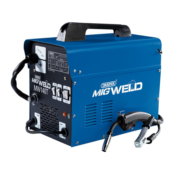
230V GAS/GASLESS
MIG WELDERS
71091-71095
IMPORTANT: Please read these instructions carefully to ensure the safe and effective use of this product and save
these instructions for future reference. This manual has been compiled by Draper Tools and is an integrated part of the
product with which it is enclosed and should be kept with it for future references.
This manual describes the purpose for which the product has been designed and contains all the necessary information
to ensure its correct and safe use. We recommend that this manual is read before any operation or, before performing
any kind of adjustment to the product and prior to any maintenance tasks. By following all the general safety
instructions contained in this manual, it will ensure both product and operator safety, together with longer life of the
product itself.
AlI photographs and drawings in this manual are supplied by Draper Tools to help illustrate the operation of the product.
Whilst every effort has been made to ensure accuracy of information contained in this manual, the Draper Tools policy
of continuous improvement determines the right to make modifications without prior warning.
Advertisement
Table of Contents


Need help?
Do you have a question about the 71091 and is the answer not in the manual?
Questions and answers