Advertisement
Quick Links
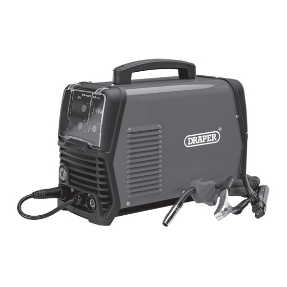
GAS/GASLESS
200A MIG INVERTER
MULTI WELDER
70046
These instructions accompanying the product are the original instructions. This document is part of the product,
keep it for the life of the product passing it on to any subsequent holder of the product. Read all these instructions
before assembling, operating or maintaining this product.
This manual has been compiled by Draper Tools describing the purpose for which the product has been designed,
and contains all the necessary information to ensure its correct and safe use. By following all the general safety
instructions contained in this manual, it will ensure both product and operator safety, together with longer life of the
product itself.
All photographs and drawings in this manual are supplied by Draper Tools to help illustrate the operation of the
product.
Whilst every effort has been made to ensure the accuracy of information contained in this manual, the Draper
Tools policy of continuous improvement determines the right to make modifications without prior warning.
Advertisement

Related Manuals for Draper MI200A


Summary of Contents for Draper MI200A
- Page 1 All photographs and drawings in this manual are supplied by Draper Tools to help illustrate the operation of the product.
- Page 2 INTRODUCTION Danger of ultraviolet radiation. 1.1 SCOPE This MIG/ARC welding machine is designed to weld ferrous metals such as steel and iron. This machine can Danger of burning splashes. perform MIG and ARC/MMA welding. This product is suitable for enthusiasts and tradespersons alike.
- Page 3 Stock No............... 70046 – Never change electrodes with bare hands or damp gloves (for ARC/MMA welders). Part No............... MI200A Rated voltage ..........230~50Hz – Keep welding cables away from power cables. Input current .............. 32A – Regularly inspect the condition of the welding, earth, and power cables for signs of damage.
- Page 4 – Before starting a weld ensure the area is clear of – In the welding environment, damaging levels of noise flammable materials. can exist. Wear hearing protection if the process dictates. – Remove any inflammables to a safe distance, especially substances likely to generate a dangerous –...
- Page 5 Fig A. If any part is damaged regulations. or missing, please contact the Draper Help Line (see back page). Do not attempt to use the product! The packaging material should be retained during the warranty period, in case the product needs to be returned for repair.
- Page 6 TECHNICAL DESCRIPTION (10) (11) (16) (15) (12) (14) (13) (17) (18) (19) (21) (23) (20) (24) (22) FIG.A (1) Power indicator. (13) Negative coupling. (2) Voltage display. (14) MIG welding torch. (3) Current display. (15) Earth clamp. (4) Wire speed. (16) MMA welding electrode holder.
- Page 7 ASSEMBLING THE insert the plug into positive coupling (11) and twist clockwise to lock. WELDER Attach the earth clamp (15) to the negative coupling (13) and twist clockwise to lock. Make sure the power supply information on the machine’s rating plate is compatible with the power 7.4 INSTALLING THE FILLER WIRE supply you intend to connect it to.
- Page 8 Note: Ensure the tip size matches the wire size prior to and tensioner (21.1). installing. (21.1) (21.2) (14.1) (14.2) (21.3) FIG. FIG. 7. Connect the welding machine to the power supply. 10. If bottled gas is required for weld it will be fitted via 8.
- Page 9 (ie. Material type, position, condition etc.) That information is well beyond the scope of this manual. Draper Tools suggest training be obtained from a third party or refer to a suitable reference book on the subject additionally; nothing can beat practice using the welder on scrap material to get a better understanding.
- Page 10 8.4 ARC WELDING, FILLER ROD Lower the electrode down toward the parent metal and strike the arc. (ELECTRODE) SELECTION – FIG. 10 The correct selection of electrode size and type will vary for each application dependent upon material thickness, material type, amperage and equipment, however as a (16.1) guide the figures below provide an indication.
- Page 11 Use of an anti-spatter spray Draper stock No.05709 will air. help to achieve a cleaner finished weld. This welding power source has a maximum material thickness capability of 5mm.
- Page 12 TROUBLESHOOTING 9.1 TROUBLESHOOTING WARNING: For your own safety, turn the switch off and remove the plug from the power supply socket. PROBLEM POSSIBLE CAUSE REQUIRED ACTION Dirty current nozzle (contact tip). Clean. May be an obstruction at the Wire not feeding despite Remove obstruction.
- Page 13 This warranty applies in lieu of any other warranty expressed or implied and variations of its terms are not authorised. Your Draper warranty is not effective unless you can produce upon request a dated receipt or invoice to verify your proof of purchase within the warranty period.
Need help?
Do you have a question about the MI200A and is the answer not in the manual?
Questions and answers