Kenwood Nexedge NX-5200 User Manual
700/800mhz vhf/uhf digital transceiver
Hide thumbs
Also See for Nexedge NX-5200:
- User manual (224 pages) ,
- Service manual (126 pages) ,
- Common function reference (476 pages)
Table of Contents
Advertisement
Advertisement
Table of Contents

Related Manuals for Kenwood Nexedge NX-5200


Summary of Contents for Kenwood Nexedge NX-5200
- Page 1 NX-5200 NX-5300 NX-5400 USER GUIDE B5A-****-00 (K)
- Page 3 NXDN™ is a protocol name for a new digital communications system using 4-level FSK technology which has been co- developed by JVC KENWOOD and Icom. This device made under license under one or more of the following US Patents: 5,502,767.
- Page 4 Terminal Descriptions Universal connector It is possible to use a resin-based cover for the Universal connector. Name Specifi cation Description Ext/Int Speaker Switch Input Hi: INT, Low: EXT Standard load 8 BTL Output + for External Speaker Standard load 8 BTL Output –...
- Page 5 THANK YOU We are grateful you have chosen KENWOOD for your land mobile radio applications. This Users Guide covers only the basic operations of your portable radio. Ask your dealer for information on any customized features they may have added to your radio. For using details instruction manual, refer to the following URL.
- Page 6 For information on Ni-MH battery recycling in your area, call (toll free) 1-800-8-BATTERY (1-800-822-8837). KENWOOD’s involvement in this program is part of our commitment to preserve our environment and conserve our natural resources.
- Page 7 For information on Li-ion battery recycling in your area, call (toll free) 1-800-8-BATTERY (1-800-822-8837). KENWOOD’s involvement in this program is part of our commitment to preserve our environment and conserve our natural resources. PRECAUTIONS •...
- Page 8 Turn the transceiver power off in the following locations: • Near explosives or blasting sites. • In aircrafts. (Any use of the transceiver must follow the instructions and regulations provided by the airline crew.) • Where restrictions or warnings are posted regarding the use of radio devices, including but not limited to medical facilities.
- Page 9 If an abnormal odor or smoke is detected coming from the transceiver, switch the transceiver power off immediately, remove the battery pack from the transceiver, and contact your KENWOOD dealer. • Use of the transceiver while you are driving may be against traffi...
- Page 10 Information concerning the battery pack: The battery pack includes fl ammable objects such as organic solvent. Mishandling may cause the battery to rupture producing fl ames or extreme heat, deteriorate, or cause other forms of damage to the battery. Please observe the following prohibitive matters. DANGER •...
- Page 11 DANGER • Do not charge the battery near fi res or under direct sunlight! If the battery’s protection circuit is damaged, the battery may charge at extreme current (or voltage) and an abnormal chemical reaction may occur. The battery may generate heat or smoke, rupture, or burst into fl...
- Page 12 IEC 60529. The fi rst numeral indicates the "dust-resistant level" and the second numeral indicates the "water- resistant" level. Note:Initial water-resistant tests and procedures are performed products upon being ordered from KENWOOD. PRECAUTIONS • The applicable standards listed above do not assure that the transceiver can be used in water.
- Page 13 • Use of any option on the transceiver not specifi ed by KENWOOD, may reduce or void the water resistant and dust resistant performance. • Read the transceiver’s instruction manual for other precautions on usage.
- Page 14 DANGER • Do not reverse-charge or reverse-connect the battery! The battery pack has positive and negative poles. If the battery pack does not smoothly connect with a charger or operating equipment, do not force it; check the polarity of the battery. If the battery pack is reverse-connected to the charger, it will be reverse-charged and an abnormal chemical reaction may occur.
-
Page 15: Table Of Contents
UNPACKING AND CHECKING EQUIPMENT Note: ◆ The following unpacking instructions are for use by your KENWOOD dealer, an authorized KENWOOD service facility, or the factory. Carefully unpack the transceiver. We recommend that you identify the items listed in the following table before discarding the packing material. -
Page 16: Installing/ Removing The (Optional) Battery Pack
INSTALLING/ REMOVING THE (OPTIONAL) BATTERY PACK Installing/ Removing the Battery Pack Do not short the battery terminals or dispose of the battery by fi re. ◆ Never attempt to remove the casing from the battery pack. ◆ Install the battery pack after cleaning the battery pack contacts and ◆... -
Page 17: Installing The (Optional) Antenna
INSTALLING THE (OPTIONAL) ANTENNA Screw the antenna into the Optional connector on the top of the antenna transceiver by holding the antenna at its base and turning it clockwise until secure. INSTALLING THE BELT CLIP If necessary, attach the belt clip Belt clip using the two supplied M3 x 8 mm binding screws. -
Page 18: Installing The Cap Over The Universal Connector
INSTALLING THE CAP OVER THE UNIVERSAL CONNECTOR 1 If you are not using an optional speaker/ microphone or headset, install the cap over Universal the universal connector. connector cap 2 Secure the cap in place using the dressing screw. INSTALLING THE (OPTIONAL) SPEAKER/ MICROPHONE OR HEADSET 1 Insert the guide of the speaker/ microphone or headset connector into the groove of the universal connector. -
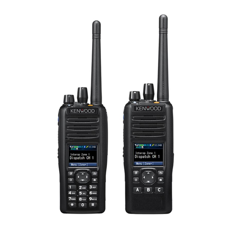
Page 19: Getting Acquainted
GETTING ACQUAINTED KEYS AND CONTROLS Antenna Speaker Microphone Standard Key model Micro SD Card SLOT Full Key model a Power switch/ Volume control Turn clockwise to switch the transceiver ON. Rotate to adjust the volume. Turn counterclockwise fully to switch the transceiver OFF. - Page 20 c Transmit/ Receive/ Battery low indicator Lights red while transmitting, green while receiving (on Conventional channels only), and orange when receiving an encoded call (i.e. 2-tone, DTMF signaling, etc.). Flashes red when the battery power is low while transmitting. Replace or recharge the battery pack when the battery power is low.
- Page 21 m Left/ Right/ Up/ Down key Press to activate its programmable function. n Back key Press to activate its programmable function. The default key setting is [Back]. o Home key Press to activate its programmable function. The default key setting is [Home]. p Keypad (Full key model only) Press the keys on the keypad to send DTMF tones.
-
Page 22: Display
DISPLAY Basic Frame Function Icon Area Main Area Key Guide Area Display Area Description Display the various function Icons ,signal Function Icon Area strength indicator and battery power indicator. Display the information of the transceiver Main Area such as Channel number and Zone namber. Key Guide Area Display the key functions (key guide). - Page 23 Icon Description Appears when the GPS function is activated. Appears when the current zone is added to the scanning sequence. is activated. Appears when you are using Scan mode. Appears when the Priority scan is in progress. Appears when the current channel is programmed as a Priority channel.
- Page 24 Icon Description Appears when the Call Diversion function is activated. Selected group is programmed as telephone IDs or RIC (Repeater Interconnect). Appears when you have entered a Tactical Group zone. Appears when the AUX A is activated. Appears when the Lone Worker function is activated.
- Page 25 © 2014 JVC KENWOOD Corporation...
- Page 26 Use only KENWOOD authorized accessories (antennas, battery packs, belt clips, Speaker/ Mics or headsets etc.): When worn on the body, always place the radio in a KENWOOD recommended clip or carrying case meant for this product. The use of other than recommended or approved body- worn accessories may result in RF exposure levels which exceed the FCC’s occupational/...
Need help?
Do you have a question about the Nexedge NX-5200 and is the answer not in the manual?
Questions and answers