
Related Manuals for Kentec Electronics XT+


Summary of Contents for Kentec Electronics XT+
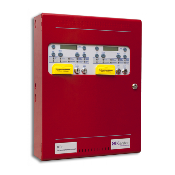
- Page 1 XT+ Releasing Control Unit Installation Manual UL Version 1.00 | December 2018 | MAN-1252KE...
- Page 2 XT+ Releasing Control Unit Installation Manual Kentec Electronics Ltd UL Version 1.00 | December 2018 | MAN-1252KE XT+ Releasing Control Unit Installation Manual Page 2...
-
Page 3: Table Of Contents
Return Material Authorization (RMA) Warranty Service Advanced Replacements Overview Fascia Buttons LED Status Indicators Keyswitches Internal Indicators and Switches Terminals Bottom Power Supply Features Batteries Installation Kentec Electronics Ltd UL Version 1.00 | December 2018 | MAN-1252KE XT+ Releasing Control Unit Installation Manual Page 3... - Page 4 3rd Stage (Released) Supv. / Abort Extract Notification Appliances 3rd Stage Alarm 2nd Stage Alarm Exting. 1 (Main) and Exting. 2 (Reserve) Bottom Terminals Kentec Electronics Ltd UL Version 1.00 | December 2018 | MAN-1252KE XT+ Releasing Control Unit Installation Manual Page 4...
- Page 5 NOTICE TO USERS, INSTALLERS, AUTHORITIES HAVING JURISDICTION, AND OTHER INVOLVED PARTIESUL Compliance Limitations Appendix A: Specifications Terminal Electrical Ratings Appendix B: Maintenance and Repair Kentec Electronics Ltd UL Version 1.00 | December 2018 | MAN-1252KE XT+ Releasing Control Unit Installation Manual Page 5...
- Page 6 Installing the Replacement Power Supply Fuse Troubleshooting Appendix C: Equipment List Model Numbers Replacement Parts Accessories Compatible Releasing Devices Special Releasing Accessories Index Kentec Electronics Ltd UL Version 1.00 | December 2018 | MAN-1252KE XT+ Releasing Control Unit Installation Manual Page 6...
-
Page 7: Compliance Information
XT+ Releasing Control Unit Installation Manual COMPLIANCE INFORMATION Underwriters Laboratories (UL) Fire Alarm Equipment Kentec Electronics Ltd The XT+ Releasing Control Unit is suitable as follows: Types of signaling services are automatic fire alarm and manual fire alarm Class B for Notification Appliance Circuits Protected Premises Unit (PPU) for Local Service, Remote Station Service, Center Station Service, Pro- prietary Service, Auxiliary Service when used with the Elite RS FACP. -
Page 8: Fm Global Technologies Llc (Fm Approvals)
• Clean agent fire extinguishing systems, NFPA 2001 • Fixed Aerosol fire extinguishing systems, NFPA 2010 FM Global Technologies LLC (FM APPROVALS) Kentec Electronics Ltd Kentec Electronics Ltd UL Version 1.00 | December 2018 | MAN-1252KE XT+ Releasing Control Unit Installation Manual... -
Page 9: Introduction
XT+ Releasing Control Unit Installation Manual INTRODUCTION Technical Support For technical support, contact Kentec Electronics, Ltd at +44 (0)1322 222121 or techsupport@kentec.co.uk. Prior to contacting technical support, have the following information available: Product part number Purchase order or order number... -
Page 10: Warranty Service
Products returned using the advanced replacement process must be received within 30 days of the RMA issue date. Kentec Electronics Ltd UL Version 1.00 | December 2018 | MAN-1252KE XT+ Releasing Control Unit Installation Manual... -
Page 11: Overview
"modules". Fascia This section describes the features of the XT+ that are located on the fascia. Kentec Electronics Ltd UL Version 1.00 | December 2018 | MAN-1252KE XT+ Releasing Control Unit Installation Manual Page 11... -
Page 12: Buttons
Initiates the releasing process, which can happen immediately or after 30 seconds, depending on the Extinguishant Release configuration. This button shall not take the place of any NFPA required manual release device(s). Kentec Electronics Ltd UL Version 1.00 | December 2018 | MAN-1252KE XT+ Releasing Control Unit Installation Manual... -
Page 13: Led Status Indicators
Mode Select Insert the key in the lock and turn it to the right to put the module into Manual mode. Internal Indicators and Switches Kentec Electronics Ltd UL Version 1.00 | December 2018 | MAN-1252KE XT+ Releasing Control Unit Installation Manual... -
Page 14: Terminals
5.25 Amp power supply is set at the factory according to input voltage requirements of the customer, either 120VAC or 240 VAC. Kentec Electronics Ltd UL Version 1.00 | December 2018 | MAN-1252KE XT+ Releasing Control Unit Installation Manual... -
Page 15: Features
Recommended battery size is 12 Ah for a typical configuration. Required battery size is mainly dependent on standby current. To determine the most appropriate battery size, use the battery calculator in LE2. Kentec Electronics Ltd UL Version 1.00 | December 2018 | MAN-1252KE... - Page 16 If needed, install that cabinet (wired close- nippled) adjacent to the unit to minimize battery lead length. Kentec Electronics Ltd UL Version 1.00 | December 2018 | MAN-1252KE XT+ Releasing Control Unit Installation Manual...
-
Page 17: Installation
Place standby batteries in the base of the unit and connect them to the power supply. Apply power to the unit from the AC source. Configure the unit using Loop Explorer 2. Test the installation. Kentec Electronics Ltd UL Version 1.00 | December 2018 | MAN-1252KE XT+ Releasing Control Unit Installation Manual Page 17... -
Page 18: Preparing For Installation
Use knockout tabs of the cabinet box to route external cabling into the unit. IMPORTANT! Drilling additional holes in the cabinet will void the product warranty. Kentec Electronics Ltd UL Version 1.00 | December 2018 | MAN-1252KE XT+ Releasing Control Unit Installation Manual... -
Page 19: Removing Cabinet Components
Settings. The power supply settings must be performed to establish the optimal charge current of the standby batteries. These power supplies can be set to operate at Kentec Electronics Ltd UL Version 1.00 | December 2018 | MAN-1252KE XT+ Releasing Control Unit Installation Manual... - Page 20 120 VAC jumper setting exists while operating the power supply at 240 VAC. High voltage is present on jumper pins. Remove AC power before changing jumper setting. Kentec Electronics Ltd UL Version 1.00 | December 2018 | MAN-1252KE...
-
Page 21: Dip Switches
DIP switches are located on the edge of the power supply. 5.25 Amp Power Supply The following figure illustrates the location of DIP switches on the 5.25 Amp Power Supply: Kentec Electronics Ltd UL Version 1.00 | December 2018 | MAN-1252KE XT+ Releasing Control Unit Installation Manual... -
Page 22: Status Indicators
CHARGER FAULT w/ abnormal 1-1 AC Power is on and 24V output is not in regulation. HEARTBEAT 1-2 The battery voltage is too high. Kentec Electronics Ltd UL Version 1.00 | December 2018 | MAN-1252KE XT+ Releasing Control Unit Installation Manual Page 22... -
Page 23: Connecting Standby Batteries
( + ) terminal of Battery 2. 5. Connect the jumper wire from the ( + ) of Battery 1 to the ( - ) of Battery 2. Kentec Electronics Ltd UL Version 1.00 | December 2018 | MAN-1252KE XT+ Releasing Control Unit Installation Manual Page 23... -
Page 24: Connecting Field Wiring
Do not route low voltage cabling through the same conduit as AC lines. AC power lines should be threaded through a dedicated conduit. Refer to the following illustration when connecting any wiring. Kentec Electronics Ltd UL Version 1.00 | December 2018 | MAN-1252KE XT+ Releasing Control Unit Installation Manual... -
Page 25: Networking Multiple Xt+ Modules
Because the fascia is hinged, route all wiring to the left as shown, so that the fascia can be opened without disconnecting the wiring. Separate high and low voltage wiring in the enclosure with a minimum gap of 0.25". Kentec Electronics Ltd UL Version 1.00 | December 2018 | MAN-1252KE... -
Page 26: 24V Power
Wiring gauge on AUX 24V outputs must be sized as a function of cable length and device load to ensure that voltage-drop of the cable does not result in less than the minimum operating voltage at the ancillary devices. Trouble Kentec Electronics Ltd UL Version 1.00 | December 2018 | MAN-1252KE XT+ Releasing Control Unit Installation Manual... -
Page 27: 1St Stage
The Supv terminals are normally-open relay contacts. They activate on any module-related supervisory (depending on configuration) and clear when all supervisories are clear. Extract Kentec Electronics Ltd UL Version 1.00 | December 2018 | MAN-1252KE XT+ Releasing Control Unit Installation Manual Page 27... -
Page 28: Notification Appliances
The 2nd stage NACs activate when all pre-release conditions have been met and the release delay countdown has started. Exting. 1 (Main) and Exting. 2 (Reserve) Kentec Electronics Ltd UL Version 1.00 | December 2018 | MAN-1252KE XT+ Releasing Control Unit Installation Manual Page 28... -
Page 29: Bottom Terminals
Reserve Cylinders LED will be illuminated. Required EOL: EOL Diode (S2029) Refer to "Access Level 3" on page 33 for extinguishant output calibration instructions. Bottom Terminals Kentec Electronics Ltd UL Version 1.00 | December 2018 | MAN-1252KE XT+ Releasing Control Unit Installation Manual Page 29... -
Page 30: Cie Serial
These terminals are used when connecting a Status Unit to the XT+. Refer to the Equipment List for model numbers of that unit. Kentec Electronics Ltd UL Version 1.00 | December 2018 | MAN-1252KE XT+ Releasing Control Unit Installation Manual Page 30... -
Page 31: Access Levels
Disablement Switch (VF1832-xx) is required for compliance with these standards. Press Enter to re-enable the outputs and restore the Disablement and Supervisory conditions. Kentec Electronics Ltd UL Version 1.00 | December 2018 | MAN-1252KE XT+ Releasing Control Unit Installation Manual Page 31... - Page 32 XT+ module and the Elite RS FACP. The display will show: Press Enter to re-enable the output and restore the Disablement condition. Kentec Electronics Ltd UL Version 1.00 | December 2018 | MAN-1252KE XT+ Releasing Control Unit Installation Manual...
-
Page 33: Set The Extinguishant Output Calibration
Press Enter, then (+) until the LCD displays: Kentec Electronics Ltd UL Version 1.00 | December 2018 | MAN-1252KE XT+ Releasing Control Unit Installation Manual... - Page 34 Press (+) to display and set the monitoring level for output 2 in the same way as output 1. IMPORTANT! After calibration of these outputs, testing should be done to confirm proper operation of the extinguishing system. Kentec Electronics Ltd UL Version 1.00 | December 2018 | MAN-1252KE XT+ Releasing Control Unit Installation Manual Page 34...
-
Page 35: System Startup
Perform the following tests to confirm operation of the power supply: 1. Apply AC and battery power to the XT+. 2. Check that the AC Normal LED is illuminated on the power supply. Kentec Electronics Ltd UL Version 1.00 | December 2018 | MAN-1252KE XT+ Releasing Control Unit Installation Manual... -
Page 36: Lamp, Display, And Buzzer Test
Verify that each field-installed device functions as expected. Configuration The XT+ can be configured via LE2. An master FACP must be configured, and then up to 15 XT+ modules can be added. Kentec Electronics Ltd UL Version 1.00 | December 2018 | MAN-1252KE XT+ Releasing Control Unit Installation Manual Page 36... -
Page 37: Times Tab
The delay between the activation of a Release Delay 0 - 60 seconds 30 seconds module and extinguishant release. Kentec Electronics Ltd UL Version 1.00 | December 2018 | MAN-1252KE XT+ Releasing Control Unit Installation Manual Page 37... -
Page 38: Disablements Tab
The trouble relay on each module can be disabled. Trouble Output Enabled or Disabled Enabled For UL compliance, this field must be set to Enabled. Kentec Electronics Ltd UL Version 1.00 | December 2018 | MAN-1252KE XT+ Releasing Control Unit Installation Manual Page 38... -
Page 39: Settings Tab
This can be used to invert the action of the Low Normal Low Pressure Switch Mode Normal Pressure Switch input. Invert Kentec Electronics Ltd UL Version 1.00 | December 2018 | MAN-1252KE XT+ Releasing Control Unit Installation Manual Page 39... - Page 40 When the Manual Release input is configured for no delay, it will override an active Abort input. When the Manual Release input is configured for pre-release delay, it will override an active Abort input and cause the countdown to resume. Kentec Electronics Ltd UL Version 1.00 | December 2018 | MAN-1252KE XT+ Releasing Control Unit Installation Manual...
-
Page 41: Notice To Users, Installers, Authorities Having Jurisdiction, And Other Involved Partiesul Compliance Limitations
Invert Abort Abort Mode Abort Hold Disable Access Level 2 > Disable Exting. Release? Enable Enable Power Supply DIP Switches OFF / ON OFF / ON Kentec Electronics Ltd UL Version 1.00 | December 2018 | MAN-1252KE XT+ Releasing Control Unit Installation Manual Page 41... -
Page 42: Appendix A: Specifications
Maximum Current Draw from Batteries Ground Fault Impedance Value 100 Ohms Temperature Range 32°F (0°C) - 120°F (49°C) Relative Humidity Up to 93%, non-condensing Kentec Electronics Ltd UL Version 1.00 | December 2018 | MAN-1252KE XT+ Releasing Control Unit Installation Manual Page 42... -
Page 43: Terminal Electrical Ratings
Two wire, RS485 connection, Data 3.3 V, current-limited, Class B, supervised Status Serial Maximum Wiring Impedance: 120 Ohms Status Pow. 24V Regulated @ 360mA Max, Power-limited Kentec Electronics Ltd UL Version 1.00 | December 2018 | MAN-1252KE XT+ Releasing Control Unit Installation Manual Page 43... -
Page 44: Appendix B: Maintenance And Repair
4. Remove Battery 1 and Battery 2 from the bottom of the XT+ Releasing Control Unit cabinet. 5. Recycle Battery 1 and Battery 2 according to the manufacturer procedures provided in the battery pack- aging. Kentec Electronics Ltd UL Version 1.00 | December 2018 | MAN-1252KE XT+ Releasing Control Unit Installation Manual... -
Page 45: Installing The Standby Batteries
Install the replacement fuse in the fuse housing and then test the power supply to determine that it operates. The following figure illustrates the fuse of the power supply: Removing the Power Supply Fuse Kentec Electronics Ltd UL Version 1.00 | December 2018 | MAN-1252KE XT+ Releasing Control Unit Installation Manual... -
Page 46: Installing The Replacement Power Supply Fuse
Troubleshooting If the configuration is corrupted on power up/reset, the configuration ROM items can be reset to their default values by performing the following procedure: Kentec Electronics Ltd UL Version 1.00 | December 2018 | MAN-1252KE XT+ Releasing Control Unit Installation Manual... - Page 47 2. Set the write-protect switch off. 3. Press both the ( - ) and Exit buttons until the System Initializing indication is displayed on the LCD. Kentec Electronics Ltd UL Version 1.00 | December 2018 | MAN-1252KE XT+ Releasing Control Unit Installation Manual...
-
Page 48: Appendix C: Equipment List
XT+ 1 Area Releasing Module w/ Cabinet Gray K1712-10 XT+ 2 Area Releasing Module w/ Cabinet Red K1712-40 XT+ 2 Area Releasing Module w/ Cabinet Gray Kentec Electronics Ltd UL Version 1.00 | December 2018 | MAN-1252KE XT+ Releasing Control Unit Installation Manual Page 48... -
Page 49: Replacement Parts
K1514-00 Battery Lead Set with fuse holder and 10A 3AG fuse for 5.25A power supply Power Supplies are required components of the XT+. Kentec Electronics Ltd UL Version 1.00 | December 2018 | MAN-1252KE XT+ Releasing Control Unit Installation Manual Page 49... -
Page 50: Accessories
Manual Extinguishant Disablement Switch K1832-40 Sequential Activator, Suitable for Releasing K1824-10 Standard cabinet, Red K1824-11 Large cabinet, Red K1824-40 Standard cabinet, Gray K1824-41 Large cabinet, Gray Kentec Electronics Ltd UL Version 1.00 | December 2018 | MAN-1252KE XT+ Releasing Control Unit Installation Manual Page 50... -
Page 51: Compatible Releasing Devices
Snap-Tite, Sevo Systems, Orient 2823A-2NB-A4F6 Chemori, Solenoid Solutions Victaulic Series 753-E FireLock Viking 11596 Viking 11595 Viking 11592 Viking 11602 Viking 11601 Viking 11591 Kentec Electronics Ltd UL Version 1.00 | December 2018 | MAN-1252KE XT+ Releasing Control Unit Installation Manual Page 51... -
Page 52: Special Releasing Accessories
XT+ Releasing Control Unit Installation Manual Special Releasing Accessories Kentec Electronics Sequential Activator K1824-10 or -40 (Red or Gray) K1824-11 or -41 (Red or Gray) FP-SA/GEN3.0 (Gray) FP-SA/GEN3.0R (Red) FP-SA/GEN3M8 (Gray) FP-SA/GEN3M8R (Red) FirePro FP-20SE (FNX-20S) Fixed Condensed Aerosol Extinguishing System Units... -
Page 53: Index
EOLR 26 Terminals 14, 23, 43-44 Fascia 11, 17, 31, 42, 48 Trouble 13, 22, 33, 36, 43, 45 Fuse 13, 42, 49 UL Version 1.00 | December 2018 | MAN-1252KE Kentec Electronics Ltd XT+ Releasing Control Unit Installation Manual Page 53... - Page 54 Index Trouble Relay 15, 38 Kentec Electronics Ltd UL Version 1.00 | December 2018 | MAN-1252KE XT+ Releasing Control Unit Installation Manual Page 54...
Need help?
Do you have a question about the XT+ and is the answer not in the manual?
Questions and answers