
Related Manuals for Spirit 1622768


Summary of Contents for Spirit 1622768
- Page 2 WARNING: ALWAYS UNPLUG THE TREADMILL FROM THE ELECTRICAL OUTLET BEFORE SERVICING THE UNIT.
-
Page 3: Table Of Contents
TABLE OF CONTENTS Table of Contents..............1 Table of Figures..............3 Description ................4 ........4 LECTRICAL ONFIGURATION 1. 1622768 Treadmill components........4 ..........5 ENERAL NFORMATION 1. Console ...............5 2. Main controller............5 3. Treadmill motor ............5 Operation................7 ..........7 INDOW ISPLAY 1. OFF Mode..............7 2. - Page 4 2. Troubleshooting Matrix..........15 Diagrams and Schematics ............. 20 APPENDIX A ..............24 1. TREADBELT ADJUSTMENT......... 24 APPENDIX B ..............26 1. TREADMILL LUBRICATION ........ 26 APPENDIX C ..............27 1. RESET SWITCH RESETTING ........ 27 APPENDIX D ..............28 1.
-
Page 5: Table Of Figures
TABLE OF FIGURES Figure 1 Operational Flowchart..........6 Figure 2 Console Layout ............20 Figure 3 Mechanical Layout..........20 Figure 4 Main Controller information & voltages....21 Figure 5 Function JK1 connector on Main Controller... 21 Figure 6 Wiring Diagram ............. 22 Figure 7 Schematic Diagram .......... -
Page 6: Description
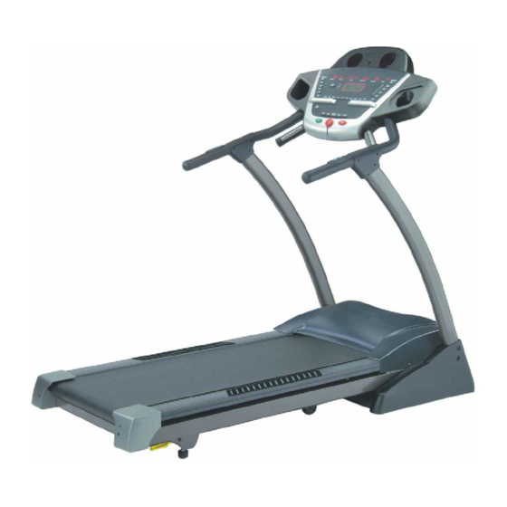
LECTRICAL ONFIGURATION Note: Electrical servicing of this treadmill is limited to board level replacement. 1. 1622768 TREADMILL COMPONENTS a) Safety key: b) Magnetic key fits in the Console to activate all functions. c) Console: Interface that controls all functions of the treadmill. -
Page 7: B General Information
ENERAL NFORMATION 1. CONSOLE a) Contains 6 windows which are twenty rows of Red-color “dots” (8high) indicate each segment of a workout. 2. MAIN CONTROLLER a) Contains power supply and control circuits. 3. TREADMILL MOTOR a) Variable speed reversing 0-90 volt DC motor. b) Has three wires red, black and green. -
Page 8: Figure 1 Operational Flowchart
Figure 1 Operational Flowchart... -
Page 9: Operation
OPERATION INDOW ISPLAY 1. OFF MODE a) If console can’t be displayed, please make sure power is on b) If power is on, the console will show up” Please install safety key to start.” 2. READY MODE a) When the treadmill is ON and the SAFETY KEY is inserted in console, (6 LED windows and twenty rows of Red-color “dots”... -
Page 10: Run Mode
4. RUN MODE a) In RUN Mode, press the “STOP” button and remove the SAFETY KEY will cause the treadmill stop instantly and enter OFF Mode. b) Display will automatically shift every 5 seconds. c) Press “Display” button to exchange the displaying of LED which includes laps of Track, Incline profile and Speed profile. -
Page 11: Distance
3. DISTANCE a) In RUN Mode, DISTANCE preset is COUNT UP. b) DISPLAY range is 0.00 to 999. c) WORK range is 0.0 to 999. d) In RUN Mode, press the “START” button that DISTANCE value will still display and save all data. If RUN Mode is entered, the distance will count up again. -
Page 12: C Function Button I N Main Mode
a) Display will automatically shift every 5 seconds. b) At the Dot Matrix window that displays profiles of speed and incline which will shift every 5seconds. UNCTION UTTON 1. READY MODE a) In “READY” mode, user could choose any programs, which include MANUAL, HILL, FATBURN, CARDIO, STRENGTH, INTERVAL, USE1, USE2, HR1and HR2 or press “START”... -
Page 13: Sleep Mode
10 preset program buttons and 6 preset buttons for rapid speed and rapid incline. 2. SLEEP MODE a) MANUELL, HILL, FATBURN, CARDIO, STRENGTH, INTERVAL, USE1, USE2, HR1 and HR2 buttons: Enter the READY Mode. b) START button: Enter the READY Mode. Enter button: Enter the READY Mode. -
Page 14: D Calibration Procedure
FAST button: Press the button to increase your speed and each increase is 0.1mph/km. If button is pressed continuously then speed increases to MAX SPEED quickly. g) SLOW button: Press the button to decrease your speed and each decrease is 0.1mph/km. If button is pressed continuously then speed decreases to MIN SPEED quickly. - Page 15 g) Set Min. speed: Press “ENTER” button to set the minimum speed that will display the value0.5 in the TIME window. Dot Matrix will display ”ADJUST MIN SPEED THEN PRESS ENTER”. h) Set Max. Speed: Press “ENTER” button to set the high speed that will display the value 20 in TIME window.
-
Page 16: Troubleshooting
TROUBLESHOOTING WARNING: ALWAYS UNPLUG THE TREADMILL FROM THE ELECTRICAL OUTLET BEFORE SERVICING THE UNIT. 1. GENERAL a) Do a visual check of all wiring and connections looking for chafed wires or lose connections. b) Make sure any wiring is safely positioned and/or secured away from moving parts. -
Page 17: Troubleshooting Matrix
2. TROUBLESHOOTING MATRIX Condition Reason Solve When turn on power, ON/OFF switch 1. Power cord don’t plug into outlet in right 1.Plug the power cord into outlet. isn’t bright. position. 2.Plug the power cord into unit. 2. Power cord don’t plug into unit. 3. - Page 18 5. Varistor of controller was broken. 5. Replace varistor or controller. 6. Reed switch of console was broken. (open) 6. Replace reed switch or console. 7. Other components are imperfection. 7. Replace console. When console didn’t insert safe key 1. Reed switch of console was broken. (short) 1.Replace reed switch or console.
- Page 19 LED has problem that would be not 1. LED light was broken. 1.Replace LED or console. bright, incomplete or imperfect. Seven segment displays have problem 1. Seven segment displays was broken. 1.Replace console and calibrate it. that would be not bright, incomplete or imperfect.
- Page 20 broken,(open) console can’t receive 5.The 12C508A was broken on the controller. 5.Replace “12C508A” or controller. the speed. 6. Computer cable of 12PIN didn’t connect into 6.Plug the cable again on controller, right position. connector and console. 7. Computer cable of 12PINwas broken. 7.Gray and purple wires got damage, replace the wires.
- Page 21 Hand pulse lost its function. 1.Hands don’t hold the hand pulse or hold the hand 1.Two hands hold the hand pulse. (No pulse displayed on monitor) pulse with single hand. 2.The connector of HANDPULSE W/WIRE and 2.Connect the wires again. Console don’t connect into position.
-
Page 22: Diagrams And Schematics
DIAGRAMS AND SCHEMATICS Figure 2 Console Layout Figure 3 Mechanical Layout... -
Page 23: Figure 4 Main Controller Information & Voltages
MOSFET M+ T O MOT OR ( RED WI RE) TO MOTOR (BLACK WI RE) FUSE 3A AC 1~AC 2 110 VAC IN 12C 508 AC OU T_ 2 AC OU T_ 1 Figure 4 Main Controller information & voltages Figure 5 Function JK1 connector on Main Controller... -
Page 24: Figure 6 Wiring Diagram
PLUG Black DOWN Brown Orange FAST Yellow CONNECTOR BREAKER SLOW (FEMALE) Green Blue Purple AC SWITCH Gray White Light blue Pink WHITE WIRE BLACK WIRE INCLINE MOTOR FRAME BASE DOWN CONTROLLER SENSOR RED WIRE 12 PIN 1150 mm MOTOR BLACK WIRE COMPUTER CABLE (LOWER) 2 pin GROUND WIRE... -
Page 25: Figure 7 Schematic Diagram
Figure 7 Schematic Diagram... -
Page 26: Treadbelt Adjustment
APPENDIX A 1. TREADBELT ADJUSTMENT The treadbelt has been factory pre-adjusted, however if during the operation: 1 /4 T U R N Figure 8 If Treadbelt slips The treadbelt is too loose: Tighten both rear roller adjusting bolts 1/4 turn clockwise using allen wrench 1/4 TUR N Figure 9 If tread belt shifts too far to the Right a) Set the treadmill speed to 3.5 mph/5.6 km. -
Page 27: Figure 10 If Tread Belt Shifts Too Far To The Left
1/4 TU R N Figure 10 If tread belt shifts too far to the Left a) Set the treadmill speed to 3.5 mph/5.6 km. b) Tighten the left adjusting bolt a 1/4 turn clockwise using allen wrench c) Wait 15 seconds: if no change; turn the right adjusting bolt a 1/4 turn counter-clockwise using allen wrench e) Repeat steps b and c until belt is centered IMPORTANT... -
Page 28: Treadmill Lubrication
APPENDIX B 1. TREADMILL LUBRICATION Your treadmill should require little maintenance other then periodically applying lubricant. Lubricating under the treadbelt will ensure superior performance and extend its life expectancy. HOW TO CHECK TREADBELT FOR PROPER LUBRICATION Lift one side of the treadbelt and feel the top surface of the treadboard If the surface is (slick) to the touch, then no further lubrication is required If the surface is dry to the touch, apply one packet of lubricant HOW TO APPLY LUBRICANT... -
Page 29: Reset Switch Resetting
APPENDIX C Tripped Normal Figure 11 Resetting Reset switch 1. RESET SWITCH RESETTING a) If the red button of reset switch is tripped, it will protrude out from the face of the switch. b) Press in the red button of the switch. c) If the red button of reset switch is not tripped, that means normal. -
Page 30: Fuse Replacement
APPENDIX D FUSE 3A Fuse Mount Figure 12 Fuse replacement 1. FUSE REPLACEMENT If your treadmill loses power or will not start, check the fuse located on the motor controller. DANGER: Turn the power switch off and unplug the treadmill to reduce the risk of an electric shock Remove the motor cover Remove and replace the fuse on the motor controller... -
Page 31: Speed Sensor Adjustment
APPENDIX E 1. SPEED SENSOR ADJUSTMENT If the monitor does not display speed or distance the speed sensor and magnet may be misaligned. Follow these steps to check and realign. Remove the motor cover Check the spacing and alignment between the magnet on the right side of the front roller and the speed sensor on the frame.
Need help?
Do you have a question about the 1622768 and is the answer not in the manual?
Questions and answers