
Subscribe to Our Youtube Channel
Related Manuals for ACR Electronics AIS Link MOB


Summary of Contents for ACR Electronics AIS Link MOB
- Page 1 Personal Locator Device (Incorporating AIS and DSC) User Manual Y1-03-0283 Rev. C...
- Page 2 The technical data, information and illustrations contained in this manual were believed to be correct at the time of print. ACR Electronics, Inc. (ACR) reserves the right to change specifications and other information contained in this manual as part of our continual improvement process.
-
Page 3: In Case Of Emergency
MOB USER MANUAL IN CASE OF EMERGENCY Use only in situations of grave or imminent danger. The MOB is intended to be fitted to a life jacket. If the MOB is correctly fitted to the life jacket, then it will automatically activate when the life jacket inflates. -
Page 4: Table Of Contents
CONTENTS IN CASE OF EMERGENCY ........................3 GENERAL ............................5 Introduction ........................... 5 Exposure to RF Electromagnetic Energy ................. 5 Warnings ..........................5 MOB OVERVIEW ........................... 6 INSTALLATION ..........................7 MMSI configuration ........................14 Self-Identification ........................ 14 User MMSI ........................... 14 OPERATION ......................... -
Page 5: General
MOB USER MANUAL GENERAL Introduction The AISLink range of products provides the user with the latest technology specifically designed for compact size and ease of operation. The MOB is intended to be fitted to a lifejacket in order to alert your vessel in the event that you fall over board. It will then plot your location on a suitable AIS equipped chart plotter. -
Page 6: Mob Overview
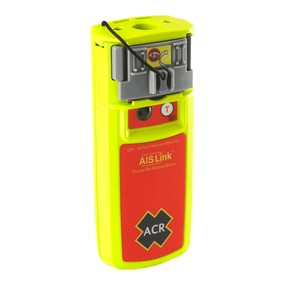
MOB USER MANUAL MOB OVERVIEW Antenna behind activation slide Arming Retainers Activation Slide “ON” Key (for manual activation) Strobe and Indicator LED “TEST/OFF” Key Activation Tape Oral Mounting Bracket Antenna Rewind Tool MOB LED (5) and “ON” (4) and “TEST/OFF” (6) 10) Programming Adaptor buttons shown in activated condition. -
Page 7: Installation
MOB USER MANUAL INSTALLATION NOTE: Be sure to load the activation tape EXACTLY as described in this section. Failure to do so may affect deployment. If your AISLink MOB is not already pre-installed into the life jacket, please carefully follow the instructions below. - Page 8 MOB USER MANUAL rear activation slide. Route the front of the activation slide along the tether and squeeze the front and rear sections tightly together. The activation tape will be trapped in place by the action of closing the front and rear sections together. ...
- Page 9 MOB USER MANUAL NOTE: When loading the activation tape, the tape must be positioned between the arming retainer and activation slide as shown below, or the MOB will fail to deploy. In all installation scenarios (A – E) below, ensure that the installed MOB is tethered to the life jacket using either of the tether attachment points (top of MOB or bottom of MOB) shown in the following images.
- Page 10 MOB USER MANUAL Note any particular jacket manufacturer’s packing requirements. Repack the bladder into the cover, following the manufacturer’s guidelines. Ensure the activation tape does not get trapped in the fastenings or tangled up. Once the MOB is fully attached to the life jacket, the device is armed. ...
- Page 11 MOB USER MANUAL B2. Load the fixing buckle with the activation tape as shown below. B3. Bond the fixing buckle to the fixing buckle patch. Ensure that the two ears of the ‘T’ are positioned on the side of the patch without the adhesive. This will ensure that when the buckle is tensioned it cannot be pulled through the adhesive patch.
- Page 12 MOB USER MANUAL attach the second reflective strip at 90 degrees to the first. Be sure to once again press down on this second reflective strip in order to adhere it securely to the bladder. Pass the activation tape around the bladder of the life jacket and then clip the MOB to the installation bracket.
- Page 13 MOB USER MANUAL D2. Load the fixing buckle with the activation tape as shown below. D3. Bond the fixing buckle to the fixing buckle patch. Ensure that the two ears of the ‘T’ are positioned on the side of patch without the adhesive. This will ensure that when the buckle is tensioned it cannot be pulled through the adhesive patch.
-
Page 14: Mmsi Configuration
MOB USER MANUAL NOTE: The reflective patches are not intended for long term external exposure. Patches will need inspecting and possible replacement following a deployment. E. Installation on non-inflatable (foam vest) life jackets: The preferred mounting method in this scenario is use of the included installation bracket to attach the MOB to existing lifejacket webbing/straps. - Page 15 MOB USER MANUAL 4.2.1 Installation The programming software for configuring the User MMSI into the MOB can be downloaded from www.acrartex.com/ by going to the AISLink MOB product page and clicking on “Configure AISLink MOB”. The software available will only allow the DSC options available in your country.
-
Page 16: Operation
MOB USER MANUAL When the programming is complete, the screen will change. Remove the MOB and check that the LED starts flashing green. Turn the MOB off by pressing the “TEST/OFF” key for one second. The LED will blink red twice. Press the <F12> key to exit the programming mode. -
Page 17: Dsc All Ship Distress Alert Transmission
MOB USER MANUAL Upon activation, the indicator LED will show eight short flashes during AIS transmission and one long flash during DSC transmission. The color of the flash will be red during position acquisition and green when the GPS position is being received. ... -
Page 18: Testing
MOB USER MANUAL Testing Routine testing of your MOB once a month is recommended to ensure it is in good working order if needed, but please follow the guidance notes below on the frequency that tests should be carried out. Please remember that each test will reduce the battery capacity slightly and reduce the operation time of your MOB during an emergency. -
Page 19: Ais Transmission Test
MOB USER MANUAL The DSC test requires that a valid MMSI has been programmed into the MOB. See section 4 for instructions on programming the MMSI. The DSC test should only be carried out a maximum of two times a year to minimize battery consumption. -
Page 20: Appendix
Electronics, Inc. authorized battery replacement center. Transport When shipping your MOB the following guidance and regulations should be followed, but you are advised to contact your nearest battery replacement center or ACR Electronics, Inc. prior to shipping as regulations may have changed. ... -
Page 21: Specifications
MOB USER MANUAL Specifications AIS transmission Transmit Power (EIRP)..................1Watt Frequency ..............161.975/162.025MHz ±500Hz Baud rate ....................9600baud Synchronisation ....................UTC Messages ........... Message 1 (Position), Message 14 (MOB status) Repetition interval................. 8 messages/minute ..............Message 14 sent twice every 4 minutes DSC Transmission Transmit Power (EIRP).................. -
Page 22: Approvals
The MOB is approved for use in the USA under CFR47 part 95K, and approved in Canada with AIS only under RSS287. European Declaration of Conformity 8.7.1 Hereby, ACR Electronics, Inc. declares that the radio equipment type AISLink MOB is in compliance with Directive 2014/53/EU. https://www.acrartex.com/support/acr-support/acr-declaration-of-conformity/ Y1-03-0283 Rev. C... -
Page 23: Limited Warranty
5 years from the date of purchase and in accordance with the following conditions. ACR Electronics, Inc. will, at its discretion, repair or replace faulty product free of charge, excluding the cost of shipping. Proof of purchase shall be required in order for a warranty claim to be valid from the original purchaser. - Page 24 Y1-03-0283 Rev. C...
Need help?
Do you have a question about the AIS Link MOB and is the answer not in the manual?
Questions and answers