Table of Contents
Advertisement
Quick Links
Advertisement
Table of Contents

Subscribe to Our Youtube Channel
Related Manuals for ACR Electronics AIS


Summary of Contents for ACR Electronics AIS
- Page 2 Please read this first! Warning: Although ACR strives for accuracy in all its publications; this material may contain errors or omissions, and is subject to change without prior notice. ACR shall not be made liable for any specific, indirect, incidental or consequential damages as a result of its use. ACR components may only be used in safety of life devices or systems, with the express written approval of ACR, as the failure of such components could cause the failure of the ACR device or system.
-
Page 3: Table Of Contents
NAUTICAST™ Installation Manual Index Page Number GENERAL INTRODUCTION ................5 1.1 Description of AIS 1.2 AIS in an Operational Environment 1.3 AIS Networks 1.4 Carriage Requirement 1.4.1 Chapter V (Safety of Navigation) Regulation 19, of the SOLAS Convention............ 8 1.4.2 Accelerated Implementation of AIS: ......................... - Page 4 History of Changes Date Version Rev. Status Comments Responsible Dimensional drawings as Annex 2003-04-30 1.0.2 Released A. Lesch Wheelmark Certificate as Annex Amendments for: Power consummation, 2003-06-30 1.0.3 Released Troubleshooting, grounding, B. Werner external fuse, battery calculation in Appendix 2004-06-03 1.0.4 Released New Approvals, new pictures...
-
Page 5: General Introduction
1 General Introduction IMPORTANT: IMO REGULATIONS MANDATE that after the physical installation has been successfully completed, all ships data and settings be entered into the AIS transponder. See Section 4 for further instructions. 1.1 Description of AIS What does the abbreviation AIS stand for? AIS stands for: “Automatic Identification System”... - Page 6 This illustration depicts a typical AIS System, where two or more AIS equipped vessels (and shore based systems) are automatically communicating with each other. On the bottom, a typical NAUTICAST™ installation in a common environment is shown. The NAUTICAST™ is connected to the vessels emergency power supply, and in connection with the VHF, and GPS-Antennas, the minimal requirements for Transponder operation are fulfilled.
-
Page 7: Ais Networks
1.3 AIS Networks The scenario below shows a full AIS coverage area (including all applications and complete shore infrastructure). The Carriage Requirement currently applies exclusively to SOLAS Vessels, but following the current international discussions on maritime security; it is common understanding that other possible AIS users will follow very soon. -
Page 8: Carriage Requirement
1.4 Carriage Requirement 1.4.1 Chapter V (Safety of Navigation) Regulation 19, of the SOLAS Convention. IMO regulations require sea vessels from a size of 300 GT (Gross Tonnage) in international and 500 GT in national waters to be equipped with an AIS-Transponder. The implementation of this legislation began on July 1, 2002 and will be enforced in the following stages: July 2002 for all vessels built from this period onwards July 2003 for all passenger ships and all tankers which were built before July 1, 2002... -
Page 9: Nauticast
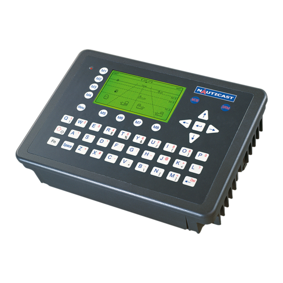
2 NAUTICAST™ 2.1 System Overview Unlike other AIS devices, the NAUTICAST™ combines all required functions into one cabinet. Additionally, the NAUTICAST™ gives the operator a number of additional features (easy mounting & installation, environmental protection and smallest dimensions). Y1-03-0204 Rev. L... -
Page 10: Installation
3 Installation 3.1 Installation Requirements General Requirements Please note that international conventions, regulations, instructions and guidelines have to be adhered to when installing the NAUTICAST™. The following points must be observed before installation can commence: Permission by the local authority to install such a device must be granted. Trained service personnel must undertake the installation. - Page 11 NAUTICAST™ Connection Diagram Note: The ACR connection box includes a fuse of 6,3A. If it is not used, then the unit has to be protected against high current by an external slow blow fuse of 6,3A. Y1-03-0204 Rev. L...
-
Page 12: General Interface Description
Components and Interfaces The diagram below illustrates which devices can be connected to the NAUTICAST™. For a detailed description of sensor connecting e.g. an existing Gyro to the NAUTICAST™ refer to Chapter 3.7 “Sensor Installation”. 3.3 General Interface Description Interface Designation Speed Direction Sensor 1... -
Page 13: Interface Nmea Description
3.4 Interface NMEA Description: 3.4.1 Sensor - Interface CH1, CH2, CH3 Refer to Chapter 3.8 for detailed information on Sensor - Interface and Configuration. 3.4.2 ECDIS – Presentation Interface CH 4 Direction Used Fields Sentence Formatters UAIS Addressed and binary broadcast acknowledgement AIS Channel assignment message in / out Acknowledge Alarm... -
Page 14: Pilot Port Ch 5
3.4.3 Pilot Port CH 5 The used sentence formatters for the pilot plug are the same as those listed for the ECDIS port. Note: A pilot input/output port is part of an AIS Class A installation. A plug connected to this port should be installed on the bridge near the pilot‟s operating position, so that a pilot can connect a Personal Pilot Unit (PPU) if required. -
Page 15: Dgps - Dgnss Channel 9
3.4.5 DGPS – DGNSS Channel 9 Field / Protocol information: All fields are provided with further information; please refer to ITU-R M.823-2 / RTCM SC 104 for detailed field information. 3.4.6 Alarm Circuit – BIIT Channel 10 The AIS requires that an alarm output (relay) must be connected to an audible alarm device or the ships alarm system, if available. -
Page 16: Sensor Interface Definitions
3.5 Sensor Interface Definitions All interface ports of the NAUTICAST™ comply with IEC-61162-1 / -2 and NMEA-0183 HS 3.0 specifications (aligned to RS422 parameters). 3.5.1 Talker drive circuits The maximum output current is I = 50mA on each port. The drive circuit meets the requirements of ITU-T V.11. -
Page 17: Sensor Notes
3.6 Sensor notes External Sensor The AIS has interfaces (configurable as IEC 61162-1 or 61162-2) for position, bottom track (BT) speed, heading and rate of turn (ROT) sensors. In general, sensors installed in compliance with other carriage requirements of SOLAS Chapter V should be connected to the AIS System.*1. -
Page 18: Sensor Hardware Installation
3.7 Sensor Hardware Installation: 3.7.1 Installation of an RS422 serial interface: In most cases, the output from a GPS is already being used by existing navigation equipment. It is possible to split an RS 422 output for two devices. If the signal becomes too low, then an NMEA splitter has to be used. -
Page 19: Sensor Software Configuration
3.8 Sensor Software Configuration 3.8.1 Introduction The AIS NAUTICAST™ requires a connection to various sensor devices. Sensor Configuration should enable compatibility with existing navigation devises aboard any vessel. This chapter deals with several ways to configure the NAUTICAST™ and to comply with the requirements of the specific sensor interfaces. - Page 20 After accessing the Sensor Configuration menu this main configuration screen is active: 19' E 12' |1> N/A|2>0.00|3>0.10nm *********** Sensor Settings ************ BaudRate Sensor1:< 4800> CRC: auto Ignored:$HC---$-----$-----$----- $-----$-----$-----$----- 1>Start Monitor> BaudRate Sensor2: 4800 CRC: auto Ignored:$HC---$-----$-----$----- $-----$-----$-----$----- 2>Start Monitor> BaudRate Sensor3: 38400 CRC: auto Ignored:$HC---$-----$-----$----- $-----$-----$-----$-----...
- Page 21 *********** Sensor Settings ************ ************************************** Please stay... analyze Sensor 1..3 this takes max. 30sec. ************************************** ---------------------------------------- | Back It is possible to interrupt this process by pressing the “Back” - Button [M8]. After the analysis is complete, the Transponder will list the data used for the AIS operation. 18' E 12' |1>...
-
Page 22: Real-Time Analysis Of Nmea Data Streams
3.8.3 Real-Time Analysis of NMEA Data Streams After these configuration procedures, an overview of the current Sensor Software Configuration has been attained. This filtered NMEA data can be analyzed further. The data source is shown on the screen below. The source can be internal or external devices, the received NMEA sentence and the channel where this data was identified (Sensor 1, 2, 3 or calculated), as well as the measured update rate. - Page 23 Each time the analysis process for sensor configuration is undertaken; a trace file (see below) is automatically generated and sent out to the ECDIS-Port. This output can also be used as a Sensor Configuration Report. $PNAUSCA,4800,4800,4800,1 $PNAUSCD,------------ Sensor Settings ------------ $PNAUSCD,Date : 06/22/2004 08:57:05 $PNAUSCD,Hardware: AIS Transponder Class A...
-
Page 24: Sensor Monitoring For Problem Analysis
3.8.4 Sensor Monitoring for Problem Analysis For specific information on a particular sensor, the NMEA input data can be monitored and is listed on the AIS display. 21' E 15' |1> N/A|2>0.00|3>0.10nm *********** Sensor Settings ************ BaudRate Sensor1:< 4800> CRC: auto Ignored:$HC---$-----$-----$----- $-----$-----$-----$----- 1>Start Monitor>... -
Page 25: Priority Handling Of Sensor Sentence
3.8.5 Priority Handling of Sensor Sentence This table shows the priority handling of NMEA sentences. The sentences which are treated with higher priority are listed first. Positioning System Source Priority HIGH Time of Position Latitude/Longitude Position accuracy Rate of Turn(ROT) Reference Datum Speed over Ground Heading... - Page 26 0 - fix not available, 1 - GPS fix, 2 - Differential GPS fix 7) Number of satellites in view, 00 - 12 8) Horizontal Dilution of precision 9) Antenna Altitude above/below mean-sea-level (geoid) 10) Units of antenna altitude, meters 11) Geoidal separation, the difference between the WGS-84 earth ellipsoid and mean-sea-level (geoid), \-\ means mean-sea-level below ellipsoid...
- Page 27 RMC - Minimum Navigation Information 11| 13 | | | $--RMC,hhmmss.ss,A,llll.ll,a,yyyyy.yy,a,x.x,x.x,ddmmyy,x.x,a,a*hh<CR><LF> Field Numbers: 1) UTC Time 2) Status, V = Navigation receiver warning 3) Latitude 4) N or S 5) Longitude 6) E or W 7) Speed over ground, knots 8) Course over Ground, degrees true 9) Date, ddmmyy 10) Magnetic Variation, degrees...
- Page 28 1:COG 5:SOG 6:SOGIn 7:SOG 8:SOGIn 9:Valid OSD - Ship Data 9 10 $--OSD,x.x,A,x.x,a,x.x,a,x.x,x.x,a*hh<CR><LF> Field Numbers: 1) Heading, degrees true 2) Status, A = Data Valid 3) Vessel Course, degrees True 4) Course Reference 5) Vessel Speed 6) Speed Reference 7) Vessel Set, degrees True 8) Vessel drift (speed) 9) Speed Units 10) CRC...
-
Page 29: Calculated Values
3.8.7 Calculated Values Processed dynamic ship data such as position, SOG etc. is generated by NMEA sentences. Exceptions: If "Calc" is displayed on the sensor analyze screen, this means that this sentence is used for calculating dynamic ship data. ROT out of HDT ROT direction left / right -/+ will be calculated out of the HDT Message, if a TIROT sentence (only “TI”-Talker devices are valid) is not connected. -
Page 30: Pin-Description Ais-Cable / Socket 50-Pins
3.9 Pin-Description AIS-Cable / Socket 50-Pins: TxA out – AIS Cable/Socket ( Sub-D 50 Plug ) TxB out + RxA in – CH5_out+ Spare RxB in + Ch4_out+ CH5_out- Spare CH4_out- CH5_gnd Spare CH4_gnd CH5_in+ Spare CH4_in+ CH5_in- Spare... -
Page 31: Pin-Description Ais-Connector
3.10 Pin-Description AIS-Connector: Black BK White WH Green GN AIS -Cable Sub-D 50 Plug Brown BR Blue Orange OR + 24 VDC/max 5A Note: Yellow YL + 24 VDC TxA out – Violet VI + 24 VDC TxB out + Gray SL(Slate) RxA ... -
Page 32: Installation Of Vhf / Gps Antennas
3.11 Installation of VHF / GPS Antennas Interference to the Ship’s VHF Radiotelephone The AIS ship borne equipment, like any other ship borne transceiver operating in the VHF maritime band, may cause interference to a ship‟s VHF radiotelephone. Because AIS is a digital system, this interference may occur as a periodic (e.g. -
Page 33: Gnss Antenna Installation
Coaxial down-leads must be used for all receiving antennas, and the coaxial screen should be connected to the ground at one end. 3.11.2 GNSS Antenna installation A Class A AIS must be connected to a GNSS antenna. Location The GNSS antenna must be installed where it has a clear view of the sky, so that it accesses the horizon freely through 360°, with a vertical observation of 5 to 90 degrees above the horizon. - Page 34 Menu „GPS Settings: Select from the Main Menu “Transponder Configuration ” Number 5. Menu is USER password protected. The default password from the factory is mentioned on your AIS display at the protection foil. Please see the appendix in your User Manual for additional password information..
- Page 35 GPS module: The screen provides means to switch the GPS Module between the „<µBlox>‟ or „<Jupiter>‟. You can force the AIS to search again for the GPS Module installed. Selecting the wrong type of GPS module may result in invalid position information and/or malfunction so that your AIS can not operate correct.
-
Page 36: Power Supply
If installations are not in compliance to this requirement we cannot guarantee NOTE: operation nor accept a warranty issue. Antenna Layout The position of the VHF and GNSS – antennas must be added to the existing antenna layout of the vessel. 3.11.3 Power Supply The NAUTICAST must be supplied from the emergency power source. -
Page 37: Starting The Nauticast
4 Starting the NAUTICAST™ Setting up your AIS Transponder for operation. NOTE: IMO REGULATIONS MANDATE THAT YOU ENTER THIS INFORMATION. After installing the antennas and hardware the following User, Voyage related and Ship Settings data needs to be entered. Upon Start-up (Applying power) enter the following information. - Page 38 19' E 13' |1>0.01|2>1.30|3>1.80nm |---------------------------------- | Menu -----| | | +- 1. Messages View | +- 2. AIS Status | +- 3. Voyage Settings -----| +- 4. Ship Settings | +- 5. Transponder Configuration Msg. | +- 6. Service Configuration | +- 7.
-
Page 39: Entering Voyage Related Data
4.2 Entering Voyage Related Data: Select from the Main Menu “Voyage Settings” Menu is USER password protected. The default password from the factory is mentioned on your AIS display at the protection foil. Please see the appendix in your User Manual for additional password information.. Enter Password and use the up and down arrows to edit Voyage Related data then press Enter or the numeric reference on the keypad to select and edit. -
Page 40: Entering Ship Settings
Voyage Related Menu Example: 18' E 12' |1>0.01|2>1.30|3>1.80nm *********** Voyage Settings ************ Cargo :<N/A or harmless> Draught :24.8m Dest. :CASABLANCA :10/13 12:31 NavStat.:Engaged in fishing ---------------------------------------- Save | Back 4.3 Entering Ship Settings: Select from the Main Menu “Ship Settings” Menu is USER password protected The default password from the factory is mentioned on your AIS display at the protection foil. - Page 41 Ship Settings Menu Example: N48^12' E 16^26' |1> N/A|2> N/A|3> N/Anm ************ Ship Settings ************* Call Sign:OEZ1234 ShipName :SOLAS 55 Ref.Points 200m 220m +--| Len (A+B): 220m 220m Beam(C+D): +-C-+D-+ Ship Type:<Cargo ship> >>> DATA OK. PRESS M5 TO SAVE DATA <<< ---------------------------------------- Save | Back...
-
Page 42: Service And User Passwords
Result: The NAUTICAST™ automatically calculates A+ B and C + D and shows length and beam of the vessel. Note: When receiving position data from large vessels, it should be considered that the position refers to the antenna mounting point upon the vessel. To ensure accurate navigation, the antenna reference points (see Other Vessels Details) should be taken into consideration when determining the vessels position. - Page 43 Your passwords must meet the following criteria: Minimum of six (6) characters, maximum of eight (8) characters Letters must be in UPPER CASE Acceptable characters are the A-Z alphabet and 0- 9 digits Password may contain both letters and numbers The User Password can be reset in the service configuration menu by entering the Service Configuration menu and creating a new password.
- Page 44 Service Password Menu Example: 25' E 18' |1>0.10|2>1.30|3>1.80nm ******* Change Service Password ******** Enter new password : Repeat new password: {Length: 6..8 characters} ---------------------------------------- | Save | Back Enter the new Password: Then push Enter (M5). Repeat the new Password: Then Push Enter (M5). A minimum of 6, a maximum of 8 characters are allowed.
-
Page 45: Troubleshooting
21' E 14' |1>0.01|2>1.30|3>1.80nm |---------------------------------- | 6-2. User Password Settings -----| | | +- 1. Change User Password View | +- 2. Change Password Protection -----| Msg. | -----| Displ| ---------------------------------------- NUM| Select->| |<-Back Enter the new Password: Repeat the new Password: A minimum of 6, a maximum of 8 characters are allowed. - Page 46 19' E 12' |1> N/A|2>0.00|3>0.10nm |---------------------------------- | Menu -----| | | +- 1. Messages View | +- 2. AIS Status | +- 3. Voyage Settings -----| +- 4. Ship Settings | +- 5. Transponder Configuration Msg. | +- 6. Service Configuration | +- 7.
-
Page 47: Alarm Codes
5.2 Alarm Codes System Reaction / Remedy Description Text Cause/Source Reaction: The transponder unit stops transmission. If Alarm ID 01 and VHF Antenna, AIS: Tx malfunction ID 02 are simultaneously displayed, then a major antenna problem has cabling arisen. Remedy: Check if the antenna is AIS compatible (156-162 MHz) and if the antenna cabling has a short circuit or is missing any contacts at the connectors. -
Page 48: Text Messages
Battery is soon out AIS: BATTERY SOON Reaction: Own ship data is lost after powering on/off the system. of capacity Remedy: consider to contact Technical Support for additional help Reaction: Conditions for enabling 1 Watt TX power are not valid. This means that: Conditions for the speed is >3kn and / or... -
Page 49: Accessories
6 Accessories The following material is included with the NAUTICAST™. 1 NAUTICAST Transponder NAUTICAST 1 installation manual, 1 user Manual Basic Kit 3 caps of plug 1 cable clamp (M5 thread) includes 1 guide plate Kit 3 angles + 3 mounting screws (screw bolt + square nut) The NAUTICAST™... -
Page 50: Technical Information
7 Technical Information PHYSICAL SPECIFIED STANDARDS Size in mm / inch (w) 201,26mm / 7,92inch IMO MSC.74(69) Annex 3 Size in mm / inch (h) 60mm / 2,36inch ITU-R M.1371-3 (Class A) Size in mm / inch (d) 281,26mm / 11,07inch IALA Techn.Clar. -
Page 51: Contact And Support Information
8 Contact and Support Information Contact your local dealer for NAUTICAST™ support. Please see our ACR Website for Service Listing. ACR Electronics Europe GmbH Handelskai 388 / Top 632 A-1020 Vienna, Austria Tel: +43 (1) 5 237 237 - 0... -
Page 52: Appendix
9 Appendix 9.1 Samples for battery calculation 9.1.1 Typical Installation GMDSS Battery size calculation for 1 hour (Battery size calculation based on the IMO regulations Chapter IV - Reg.13) Ship Name QMIII Battery capacity 230Ah Battery Type 2x (12V / 135) Area A1, A2, A3 Battery located in battery chest on observation deck Qty. -
Page 53: Drawings And Approvals
Y1-03-0204 Rev. L... - Page 54 [9,685] [5,728] 145.5 Y1-03-0204 Rev. L...
- Page 55 Y1-03-0204 Rev. L...
- Page 56 Y1-03-0204 Rev. L...
- Page 57 Y1-03-0204 Rev. L...
- Page 58 Y1-03-0204 Rev. L...
- Page 59 Y1-03-0204 Rev. L...
- Page 60 Y1-03-0204 Rev. L...
- Page 61 Y1-03-0204 Rev. L...
- Page 62 GPS 4 PROCOM RECEIVING ANTENNA 2622 DRAWING NO. SCALE Y1-03-0204 Rev. L...
- Page 63 Y1-03-0204 Rev. L...
- Page 64 Storage Temp. -45°C ~ +100°C Vibration Sine sweep 1g(0-p)10~50~10Hz each axis 20dB Gain Humidity 95%~100%RH Weatherproof 100%Waterproof Marine BBT Active GPS Antennas ACR ELECTRONICS INC. w/5 Meter Coax & TNC Male Connector 2637 (28dB Gain) or 2639 (20dB Gain) Y1-03-0204 Rev. L...
- Page 65 Y1-03-0204 Rev. L...
- Page 66 Y1-03-0204 Rev. L...
- Page 67 Y1-03-0204 Rev. L...
- Page 68 Y1-03-0204 Rev. L...
- Page 69 Antenna Width Dimensions: Antenna Tip, plastic cover. Antenna Whip, 17-7PH SS, Electro polished Base, Plating Nickel/Chrome Mounting Hole, Dimension Detail SHEET ACR PART NUMBER ACR ELECTRONICS INC. 5757 Ravenswood Road 2628 Fort Lauderdale, FL 33312 Y1-03-0204 Rev. L...
- Page 70 4.) Coil housing – Aluminum White. 5.) Antenna Connector – SO- 239, female. 6.) Locking washer and nut. 7.) Mounting bracket 8.) Set screw x2. SHEET ACR PART NUMBER ACR ELECTRONICS INC. 5757 Ravenswood Road 2628 Fort Lauderdale, FL 33312 Y1-03-0204 Rev. L...
- Page 71 Y1-03-0204 Rev. L...
- Page 72 fiberglass tube. Height 0,97m Weight 0,5 kg Wind rating 55 m/s = 125 mph Finish Polyurethane lacquer, white Temperature range -40°C, +50°C;+ -28 °F, +122°F Antenna VHF GPS Combo 2624 DRAWING NO. Y1-03-0204 Rev. L ACR Electronics, Inc. SCALE...
- Page 73 Y1-03-0204 Rev. L...
- Page 74 Y1-03-0204 Rev. L...
- Page 76 I, p. 706), did undertake the relevant type approval procedures for the equipment identified below which was found to be in compliance with the Navigation requirements of Marine Equipment Directive (MED) 96/98/EC and the last modification by Directive 20091261EC. r"7 Manufacturer ACR Electronics Inc. \, .a,-, Aciciress 5757 Ravenswood Road. t f , FORT LAUDERDALE, FL 3331?6645, USA "/...
- Page 77 Page2o'f 2 EC TYPE EXAMINATION CERTIFICATE No. BSH/461214321220109 Gomponents necessary for operation: Components necessary fof Part No. Remarks operation 2607 Software-Version: 2.0.S1 05 NAUTICASTTM AIS 2640 Connection Box 2639 GPS Antenna AIS-A W/SM Coax VH-3200 VHF Stainless Steel Whip 2628 Antenna 91.4cm (36in) or equivalent The intemal GPS sensor of the NAUTICASTTM AIS is used as backup sensor for position reporting...
- Page 81 ACR Electronics Europe GmbH hat ein Qualitätsmanagement System nach ISO 9001:2000 implementiert, und ist seit Juli 2003 ISO-zertifiziert. ACR Electronics Europe GmbH maintains a Quality Management System according to ISO 9001:2000, and received ISO certification in July 2003. ACR Electronics Europe GmbH...
- Page 82 ACR Electronics Europe GmbH hat ein Qualitätsmanagement System nach ISO 9001:2000 implementiert, und ist seit Juli 2003 ISO-zertifiziert. ACR Electronics Europe GmbH maintains a Quality Management System according to ISO 9001:2000, and received ISO certification in July 2003. ACR Electronics Europe GmbH...
- Page 83 ACR Electronics Europe GmbH hat ein Qualitätsmanagement System nach ISO 9001:2000 implementiert, und ist seit Juli 2003 ISO-zertifiziert. ACR Electronics Europe GmbH maintains a Quality Management System according to ISO 9001:2000, and received ISO certification in July 2003. 4 Antenna...
- Page 84 ACR Electronics Europe GmbH hat ein Qualitätsmanagement System nach ISO 9001:2000 implementiert, und ist seit Juli 2003 ISO-zertifiziert. ACR Electronics Europe GmbH maintains a Quality Management System according to ISO 9001:2000, and received ISO certification in July 2003. ACR Electronics Europe GmbH...
- Page 85 ISO 9001:2000 Zertifizierung / ISO 9001:2000 Certification ACR Electronics Europe GmbH hat ein Qualitätsmanagement System nach ISO 9001:2000 implementiert, und ist seit Juli 2003 ISO-zertifiziert. ACR Electronics Europe GmbH maintains a Quality Management System according to ISO 9001:2000, and received ISO certification in July 2003.
- Page 86 Quick Replacement Guide Inland AIS 1. Prepare the following tools: Screwdrivers, spanners, User Password: [your personal password] Write down the current configuration (Should be written to you user manual - Appendix 7.3. settings here: The factory default password is on the display foil) BaudRate Sensor1: BaudRate Sensor2: 2.
- Page 87 Quick Replacement Guide Inland AIS Service Configuration: Menu Press 6.Service Configuration Press [ServicePassword] Press Enter 9. Check the functionality Type in Press Menu (Default Factory Password) 2.AIS Status Press 4.Change DAC / ENI Press 2.Own Ship Data DAC is 200 for Europe, ENI - type in the number from Press your filled in tabel: You should see your Own Ship Data with...
Need help?
Do you have a question about the AIS and is the answer not in the manual?
Questions and answers