ACR Electronics NAUTICAST AIS INLAND Manual
Automatic identification system
Hide thumbs
Also See for NAUTICAST AIS INLAND:
- User manual (126 pages) ,
- Manual (105 pages) ,
- Installation manual (100 pages)
Table of Contents
Advertisement
Quick Links
Advertisement
Table of Contents

Related Manuals for ACR Electronics NAUTICAST AIS INLAND


Summary of Contents for ACR Electronics NAUTICAST AIS INLAND
- Page 2 Please read this first! Warning: Although ACR strives for accuracy in all its publications; this material may contain errors or omissions, and is subject to change without prior notice. ACR shall not be made liable for any specific, indirect, incidental or consequential damages as a result of its use. ACR components may only be used in safety of life devices or systems, with the express written approval of ACR, as the failure of such components could cause the failure of the ACR device or system.
-
Page 3: Table Of Contents
NAUTICAST™ ......................5 TARTING THE Initial Set Up of the NAUTICAST™ for operation ..............5 Entering the MMSI / IMO / DAC / ESN Numbers ............... 6 Entering Ship Settings ....................... 8 Entering Voyage Related Data ....................9 Service and User Passwords ....................13 NAUTICAST™... - Page 4 History of Changes Date Version Rev. Status Comments Responsible 2005-11-01 1.0.0 Released Initial Release A. Lesch 2006-07-25 1.0.1 Released Editorial work M.D‟Arcangelo 2006-11-06 1.0.2 Released Screen Display Updates M.D‟Arcangelo Update according to VTT&T, Adaptation for new function in Software 2.0.S116.W225, Factory Password handling, C.
-
Page 5: Starting The Nauticast
1 Starting the NAUTICAST™ Initial Set Up of the NAUTICAST™ for operation NOTE: AUTHORITIES MANDATE THAT YOU ENTER THIS INFORMATION. After installing the antennas and hardware the following User, Voyage related and Ship Settings data needs to be entered. Upon Start-up (Applying power) enter the following information. a) Enter MMSI Number - See paragraph 1.2 on entering information. -
Page 6: Entering The Mmsi / Imo / Dac / Esn Numbers
Entering the MMSI / IMO / DAC / ESN Numbers Select from the Main Menu “Service Configuration” Number 6. The default password from the factory is mentioned on your AIS display at the protection foil. (see Appendix 7.3 for password information). - Page 7 21' E 14' |1> N/A|2>0.00|3>0.10nm ********** Change MMSI / IMO *********** MMSI :119302468 IMO No.:303174162 ---------------------------------------- NUM| Save | Back Select Submenu 4 “Change DAC / ESN” with cursor button [Up] & [Down] by pressing No. 4 on the keyboard. 21' E 14' |1>0.01|2>1.30|3>1.80nm |----------------------------------...
-
Page 8: Entering Ship Settings
Entering Ship Settings Select from the Main Menu “Ship Settings” Menu is USER password protected. The default password from the factory is mentioned on your AIS display at the protection foil. (see Appendix 7.3 for password information). Enter Password and use the up and down arrows to edit Ship Settings then press Enter or the numeric reference on the keypad to select and edit. -
Page 9: Entering Voyage Related Data
GPS ANTENNA location on ship (is x in above Menu example) is located 200 meters from bow (A) and 33 Meters from Starboard side (D). Note: If no external GPS is connected, then enter same data as for internal GPS. External GPS antenna reference point must be filled in before you can save. - Page 10 Sub Menu 18' E 12' |1>0.01|2>1.30|3>1.80nm |---------------------------------- | 3. Voyage Settings -----| | | +- 1. General Settings View | +- 2. Cargo / Voyage | +- 3. Persons on Board -----| +- 4. Destination Msg. | -----| Displ| ---------------------------------------- NUM|Select->| |<-Back Select Submenu 1 “General Settings”...
- Page 11 Select Submenu 2 “Cargo/Voyage Settings” with cursor button [Up] & [Down] or by pressing No. 2 on the keyboard. N48^12' E 16^26' |1> N/A|2> N/A|3>0.00nm ******** Cargo/Voyage Settings ********* ERI ship type :<Vessel, type unknown> SOLAS shiptype: N/A or no ship Cargo type : - - - Blue cones...
- Page 12 Mask input: Scroll the Data Fields with [Enter] and input the UN destination codes as well as the ETA (estimated time of arrival) data. Save the new settings by pressing [Save], and return to the Main Menu Screen by pressing [Exit]. Press [Exit] to return to the Main Menu without saving any changes.
-
Page 13: Service And User Passwords
Service and User Passwords WARNING: It is very important that the Service password not be lost. The default password from the factory is mentioned on your AIS display at the protection foil. (see Appendix 7.3 for password information). Keeping the password in a second location may be wise. Memorizing the password is best. - Page 14 Service Menu Example: N48^12' E 16^26' |1> N/A|2>0.00|3>0.00nm |---------------------------------- | 6. Service Configuration -----| | | +- 1. Change Service Password View | +- 2. User Password Settings | +- 3. Change MMSI / IMO -----| +- 4. Change DAC / ENI | +- 5.
- Page 15 Changing the User Password Select Submenu 2 “User Password Settings” with cursor button [Up] & [Down] by pressing number 2 on the keyboard. 21' E 14' |1>0.01|2>1.30|3>1.80nm |---------------------------------- | 6. Service Configuration -----| | | +- 1. Change Service Password View | +- 2.
-
Page 16: Nauticast™ Inland Ais User Interface
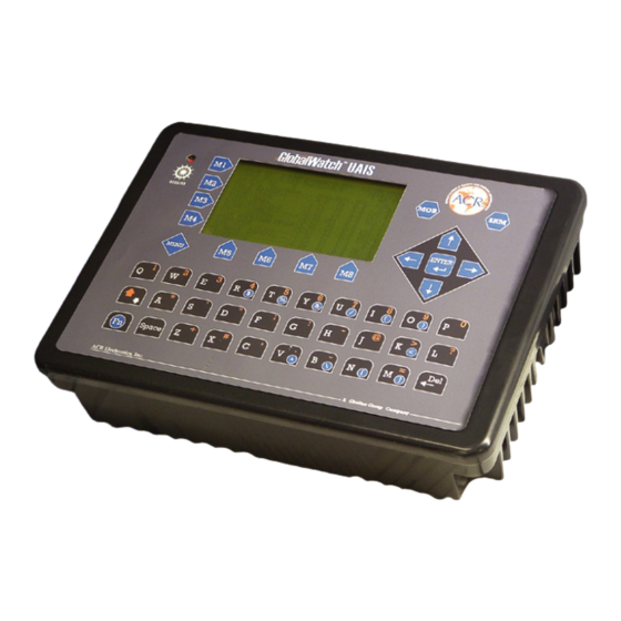
2 NAUTICAST™ Inland AIS User Interface Safety Keys Display Soft Keys [M1] – [M8] Navigation Screen Header (1 or 4 lines) Ship Details 12 lines Menu Structure 14 lines Cursor Cross Keyboard Enter Key NAUTICAST™ Keyboard The NAUTICAST™ is fitted with a full alphanumeric keyboard, with the following functions: By pressing any key on the keyboard the letters are addressed. -
Page 17: Explanation Of The Num-Locked And [Num] Functions
Explanation of the Num-Locked and [NUM] Functions The NUM-Locked function is enabled after pressing the Function [Fn] Key and the Shift [] Key. It is possible to disable the Num-Lock Function by pressing the Shift [] Key. NOTE: The NAUTICAST™ automatically changes the keys “Q” through to “P” to numerical input when the current application requires numbers, rather than letters to be input. -
Page 18: Nauticast™ Screens
3 NAUTICAST™ Screens NAUTICAST™ The advanced version of the offers three display modes: - Standard screen, automatically visible Navigation Screen - Visible after pressing the [Menu] Soft Key Menu Structure - The Graphical User Interface is visible after pressing the [M2] Soft Graphical User Interface Key (new mode) Navigation Screen... -
Page 19: Own Vessel Data
3.1.1 Own Vessel Data LAT:N 1°27.845'ExtSOG:34.6kn 05/26/06 LON:E 0°21.289'ExtCOG:173.0° 10:52:26 LAT: Latitude LON: Longitude The actual UTC - date (MM.DD.YY) and time (hh.mm.ss) are displayed on the top Date: right hand corner of this view. IntGPS: 3D A/ ExtHDT:222° Reg6 IntGPS Indicates normal or differential mode of GPS position. -
Page 20: Other Vessel Data
3.1.2 Other Vessel Data 001/021..SHIPNAME..RNG.BRG..SOG..COG.. (E.g: Vessel 01 of 021) current or selected Vessel/ Total number of Vessels 001/021 (max. 256 Vessels) Name of the Ship and AIS – Type: Cl-A: SOLAS Class-A Ship ShipName: Cl-B: Leisure Craft Base: Base station SAR : Search and Rescue Aircraft Vessel Range Note: The vessel closest to own ship, or where position data is unknown... -
Page 21: Other Vessel Details
3.1.4 Other Vessel Details This screen shows the Dynamic, Voyage and Vessel Related Data, which is currently being transmitted by a previously selected vessel. N48°12' E 16°26' |1> N/A|2> N/A|3>1.80nm Time 2:07 ------------------ POS:001/021 LAT : S 74 50.231' LON :W 9 34.192' Heading :77 ROT :-0.2... - Page 22 Reference Point (in meters): This information indicates the Reference Point of the used GPS Antenna onboard the vessel. RefPoint:A190 B120 C10 D<63m 190m 120m >63m (means more than 63m in the case of a very large vessel) Vessels Cargo: Indicates the type of cargo on board. N/A or harmless Further Vessel Details: Draught : 3.3m...
-
Page 23: Menu Structure
Menu Structure To call up the Main Menu, press the [Menu] button once, and all Submenus are displayed. The cursor position indicates the selected submenu. Menu navigation is achieved by pressing the [Up] or [Down] keys to select, and then by pressing [Enter] to confirm the desired Submenu selection. -
Page 24: Messages
Sub-Menus OverviewMessages N48^12' E 16^26' |1> N/A|2>0.00|3>0.00nm |---------------------------------- | 1. Messages -----| | | +- 1. Write Addressed SRM View | +- 2. Write Broadcast SRM | +- 3. Lock Request -----| +- 4. Inbox History | +- 5. Inbox SRM Msg. -
Page 25: Ship Settings - (User Password Protected)
3.4.4 Ship Settings – (User Password Protected) N48^12' E 16^26' |1>0.00|2>0.00|3>0.00nm *********** Convoy Settings ************ Call Sign: ShipName : Ref.Points +--| Len (A+B): Beam(C+D): +-C-+D-+ [dm]: Beam [dm]: >>> Reference point must be entered ---------------------------------------- | Back 3.4.5 Transponder Configuration – (User Password Protected) 19' E 12' |1>... -
Page 26: Display Settings
3.4.7 Display Settings 21' E 15' |1>0.10|2>1.30|3>1.80nm *********** Display Settings *********** Mode +-[*] Day +---- Brightness:<9> [*********] +---- Contrast [****** +-[ ] Night +---- Brightness: 3 [*** +---- Contrast ---------------------------------------- NUM|DayNight| | Back 3.4.8 Graphical Display Settings N48^12' E 16^26' |1> N/A|2>0.00|3>0.00nm |---------------------------------- | 8. -
Page 27: Sub-Menus Detailed
Sub-Menus Detailed 3.5.1 Messages N48^12' E 16^26' |1> N/A|2> N/A|3>0.00nm |---------------------------------- | 1. Messages -----| | | +- 1. Write Addressed SRM View | +- 2. Write Broadcast SRM | +- 3. Lock Request -----| +- 4. Inbox History | +- 5. Inbox SRM Msg. - Page 28 a) Writing an Addressed Message To write a Safety Related Message first select an addressee from the Vessel Listing. This is possible by using the cursor buttons [Up] and [Down], and confirming the selection with [Enter] or [Select]. LAT:N 48°12.177'IntSOG:0.0kn 02/25/2008 LON:E 16°26.166'IntCOG:0.0°...
- Page 29 Dynamic Keys: Addressed Message Editor Send Message Send Message [M5] [Send] [Enter] Select Transmission [M6] [Channel] Channel Select Transmission [M7] [Channel] Channel Return Vessel [M8] [Back] Listing c) Confirmation of Sent Addressed Message The confirmation screen shows the successful message transmission and indicates which channels (AIS1 or AIS2) were used.
- Page 30 It is possible, that the recipient‟s Transponder could not receive the message at all, and in this case the following screen is displayed. It is then recommended to resend the message. Unsuccessful Message Confirmation (no acknowledgement) 19' E 12' |1>0.10|2>1.30|3>1.80nm ---------------------------------------- ++++++++++++++++++++++++++++++++++++++++ Transmission Status...
- Page 31 e) Confirmation of Broadcast Sent Message This Confirmation Screen shows that the message was successfully transmitted on the Broadcast Setting. By pressing [Back] the user automatically returns to the Message Editor for further Messaging. The [SendTo] returns the user to the Vessel Listing, with the option of further Message Writing to individual vessels.
- Page 32 f) Long Range Interrogation Mobile, and shore-based stations have the ability to interrogate vessels and make requests for information over the “Long Range Interface”. The interrogated vessel can either reply in automatic, or in manual mode. The interrogation request is displayed in both modes. The arrival of a Long Range Interrogation Request is indicated by: 1L on the top right hand corner of the Navigation Screen.
- Page 33 Dynamic Keys: LRI in the Inbox History (automatic mode) Return Confirms that LRI [M5] [OK] [M8] [Back] has been seen Message Menu Send Addressed Message [M7] [Reply] sender Upon activation of the [OK] button, the user confirms that he has been notified of a current Transponder system interrogation.
- Page 34 g) Inbox History The Inbox History provides a means to reading incoming messages and alarms. The messages are listed in chronological sequence. The message type (SRM, ALR or LRI), Status, Time, Message Text Preview and MMSI Number of sender are shown in this overview screen. To select a message navigate with the cursor [Up] or [Down] –...
- Page 35 Inbox History: Message and Alarm Types and Status Definition: 19' E 13' |1>0.10|2>1.30 * 1S1A ************ Inbox History ************* ASRM 13:43 PIRATE ATTACK! 5264 ASRM*13:42 HIGH WINDS IN AREA! 5004 13:40 external EPFS lost ALR!*13:38 general failure ALR! 13:39 no sensor pos in use26 13:43 11/21 ------------------ POS:01/05 AddressedSRM 5264...
- Page 36 ASRM – Reading Incoming Addressed Safety Related Messages: 26' E 20' |1>0.10|2>1.30|3>1.80nm ************** Inbox SRM *************** ASRM*17:39 CAPTAIN IS LOST 5004 ASRM 16:26 ROUGH SEA! 5022 17:39 11/26 ------------------ POS:01/02 AddressedSRM 5004 Text:CAPTAIN IS LOST Channel:AIS1 ---------------------------------------- Reply Back ASRM: Information Time 17:39...
- Page 37 ALR – Reading Incoming Alarms: 27' E 21' |1>0.10|2>1.30|3>1.80nm ************** Inbox ALR *************** ALR! 17:36 no valid COG information 17:36 11/26 ------------------ POS:01/01 [!] ALARM ID:30 no valid COG information ---------------------------------------- | Back ALR: Information Time 17:36 Date 11/26 (mm.dd) 01/1 Message Type ALARM...
- Page 38 Dynamic Keys: Broadcast Message Editor Send Message Send Message [M5] [Send] [Enter] Return to Messages [M8] [Back] Menu RIS IDENTIFIER/ LOCATION CODE Data Elements The full Location Code has the following elements: UN Country code (2 digits) UN Location code (3 digits) Fairway section No.
-
Page 39: Ais Status
Water Level Message This message is sent by base stations to give water level information to all vessels in a certain area. The AIS can show up to 120 message entries. Messages are sorted by country code and gauge ID, which is the unique identification of the measuring point. Information from same gauge will be overwritten by the latest message. - Page 40 Mod.: AIS Transmission Mode Autonomous Assigned Interrogation/Polled Mode Unknown Used Channel AIS1, AIS2 Syn.: (UTC source) UTC direct UTC indirect Sync to Base Sync to mobile with the most received stations (Semaphore) Total number of all received stations by the individual vessel. RXVe: MMSI number of the individual vessel.
- Page 41 Reference Point (in meters): This information indicates the Reference Point of the used GPS Antenna onboard the vessel. RefPoint: A190 B120 C10 D>63m 190m 120m >16m Vessels Cargo: Indicates the type of cargo on board N/A or harmless Further Vessel Details: Draught : 3.3m Dest : HAWAII...
-
Page 42: Voyage Settings (User Password Protected)
22' E 16' |1>0.10|2>1.30|3>1.80nm ************* Version Info ************* ### ### # # # # ## #### # #### ##### # # ### # ### Hardware: AIS Transponder Class A R4 J Software: 2.0.S116.nnnn SW Stamp: Month Day Year Date Modem HW: Issue J SeCo:n Modem SW: 01.10.nn Battery: OK... - Page 43 The password query field appears. Input new User Password and press [Enter]. 31' E 24' |1>0.01|2>1.30|3>1.80nm ---------------------------------------- ++++++++++++++++++++++++++++++++++++++++ User password protected! Please enter user password: ++++++++++++++++++++++++++++++++++++++++ ---------------------------------------- | Enter | Exit ++++++++++++++++++++++++++++++++++++++++ 18' E 12' |1>0.01|2>1.30|3>1.80nm |---------------------------------- | 3. Voyage Settings -----| | | +- 1.
- Page 44 N48^12' E 16^26' |1>0.00|2>0.00| * 2S ******* General Settings / Tx1W ******** Draught[x.xx m]:N/A Airdraught[cm] :N/A NavStat. : Undefined 1 Watt : Off > NavStat : NOK (Moored) > SOG OK ( <3kn ) > ShipType : NOK (Tanker) ---------------------------------------- NUM| Save | Exit...
- Page 45 Select Submenu 3 “Persons on Board” with cursor button [Up] & [Down] or by pressing No. 2 on the keyboard. 18' E 12' |1>0.01|2>1.30|3>1.80nm ************* PoB Settings ************* Crew Members:0-254 (255 = unknown = default) Passenger :0-8190(8191= unknown = default) S.
- Page 46 Input String: Direct input of the destination string. ETA(estimated time of arrival) has to be entered separately 18' E 12' |1>0.01|2>1.30|3>1.80nm ************* Destination*************** use mask [ ]/[*] input string Destination :NLDOR02552LEUVE00000 ETA(MMDDhhmm) :10/31 10:05 ---------------------------------------- Save | Exit Mask input: Scroll the Data Fields with [Enter] and input the UN destination codes as well as the ETA (estimated time of arrival) data.
-
Page 47: Ship Settings (User Password Protected)
After the Voyage Settings have been input and saved, this screen appears. [Exit] takes the user back to the Main Menu. 30' E 24' |1>0.10|2>1.30|3>1.80nm ---------------------------------------- ++++++++++++++++++++++++++++++++++++++++ Data saved. ++++++++++++++++++++++++++++++++++++++++ ---------------------------------------- | <-Exit 3.5.4 Ship Settings (User Password Protected) Select “Ship Settings” with cursor button [Up] & [Down] or press No. 4 on the keyboard. NOTE: Please see Appendix 7.3 for password information 23' E 16' |1>0.01|2>1.30|3>1.80nm... - Page 48 Enter Call Sign: E.g: OEZ1234 Enter Ship Name: E.g MV INLAND SHIP NOTE: The reference point is defined by the 4 lengths A, B, C and D. = the distance from bow to the antenna = the distance from the antenna to the stern = the distance from the port side to the antenna = the distance from the antenna to the starboard side The following example should illustrate how the fields Len and Beam (always the complete convoy)
- Page 49 After the Ship Settings have been input and saved, this screen appears. [Exit] takes the user back to the Main Menu. 30' E 24' |1>0.10|2>1.30|3>1.80nm ---------------------------------------- ++++++++++++++++++++++++++++++++++++++++ Data saved. ++++++++++++++++++++++++++++++++++++++++ ---------------------------------------- | <-Exit GPS Antenna Mounting It is important to input the exact mounting position of the GPS Antenna on the vessel as this influences the accuracy of the displayed target in an ECDIS.
-
Page 50: Transponder Configuration (User Password Protected)
3.5.5 Transponder Configuration (User Password Protected) The Configuration Menu allows the user to alter the hardware-based parameters. User Password Configuration is also undertaken here. Accessing the Configuration Settings: The Configuration Menu is User Password protected. NOTE: Please see Appendix 7.3 for password information. N48^12' E 16^26' |1>0.00|2>0.00|3>0.00nm |---------------------------------- | 5. - Page 51 Incorrect User Password Input If the incorrect User Password is input, the screen below appears. 34' E 27' |1>0.10|2>1.30| * 1A1L ---------------------------------------- ++++++++++++++++++++++++++++++++++++++++ Access denied! ++++++++++++++++++++++++++++++++++++++++ ---------------------------------------- | <-Exit Dynamic Keys: User Password Input (Access Denied) Return to Vessel Listing [M5] [Exit] a) Change User Password (for initial NAUTICAST™...
- Page 52 33' E 27' |1>0.10|2>1.30| * 1A1L ********* Change User Password ********* Enter new password: ***** Repeat new password: ***** {Length: 6..8 characters} ---------------------------------------- Enter | Back Dynamic Keys: Initial User Password Setting Confirm User Return to Menu [M5] [Enter] [M8] [Back] Password Input Configuration...
- Page 53 The new User Password configuration has been saved. 33' E 27' |1>0.10|2>1.30| * 1A1L ---------------------------------------- ++++++++++++++++++++++++++++++++++++++++ Data saved. ++++++++++++++++++++++++++++++++++++++++ ---------------------------------------- | <-Exit b) Region Settings A Region is a defined area, with specific VHF parameters, which are sent out by Vessel Traffic Service Stations (VTS), and received via Digital Selective Calling (DSC) or AIS.
- Page 54 Overview of Region Settings Region Number Number of pre-defined Region Name Status of Region Setting - OK: Stored and Valid Valid A: Addressed Channel Management (Msge. 22) A:AddrChM Source Source: VTS via AIS B: Broadcast Channel Management B:BcastChM (Msge. 22) Source: VTS via AIS C: AIS Channel Assignment Sentence C:AIS_ChAs...
- Page 55 Input Modes for New Regions Data Field Field Description Input Modus Additional Information NE LAT(1) Latitude N/E corner Manual Input Degrees and minutes NE LON(1) Longitude of N/E corner Manual Input Degrees and minutes SW LAT(2) Latitude of S/W corner Manual Input Degrees and minutes SW LON(2)
- Page 56 d) Interrogation Settings This screen allows settings for modes of response to Long Range Interrogation Requests (LRI). It is possible to set the AIS station to respond automatically or manually to LR Interrogations, and determine which vessel data may be interrogated. It is further possible to reply to incoming LRI‟s. Long Range Interrogation Settings: 19' E 13' |1>0.10|2>1.30|3>1.80nm...
- Page 57 Replying to a Long Range Interrogation Request: The arrival of an LRI is shown in the Navigation Screen (top right hand corner: * 1L The detailed LRI is automatically stored in Menu 1:Messages, Submenu: 6 Inbox LRI, where the request can be read and replied to. LAT:N 20.261'ExtSOG:34.6kn LON:E...
- Page 58 e) Sensor Settings Within this service password protected menu the NAUTICAST™ offers the following configuration options: Set up data speed 4800/9600/38400 baud. Monitor the connected sensor inputs for each sensor channel. Verify and edit the Sensor Configuration on the display screen. Analyze the information received from the connected sensor devices.
- Page 59 Pos.Pinning: The screen provides the means to switch the position pinning function of the internal GPS receiver <On> and <Off>. For vessels operating with SOG < 0,3 knots it is recommended to switch position pinning Off. Otherwise the internal GPS receiver may deliver wrong position information. The data input field is fitted with the recommended default value (<on>).
-
Page 60: Service Configuration (Service Password Protected)
3.5.6 Service Configuration (Service Password Protected) The Service Configuration Menu allows initial configuration of the Service Password, Password Settings (on/off), MMSI/IMO Numbers and the option of resetting the NAUTICAST™ to Factory Settings. The Service Password is required in order to enter the Service Configuration Menu. This is a higher security level than can be reached with the User Password and therefore ensures that the Service Configuration is protected, and limited to authorized service personnel. - Page 61 f) Change Service Password This screen provides a means to individually configure the Service Password. This password differs from the User Password as it allows the user access to the Menu „Service Configuration“. A minimum of 6, a maximum of 8 characters are allowed. The process of configuring the Service Password is identical to that of User Password configuration (see Menu 5: Configuration, Submenu 1: Change User Password).
- Page 62 g) User Password Settings 24' E 18' |1>0.10|2>1.30|3>1.80nm |---------------------------------- | 6-2. User Password Settings -----| | | +- 1. Change User Password View | +- 2. Change Password Protection -----| Msg. | -----| Displ| ---------------------------------------- NUM| Select->| |<-Back Change User Password Protection: This function allows the user to enable or disable the User Password Query Function.
- Page 63 h) Changing the MMSI / IMO / DAC / ESN Numbers Mentioned DAC and ESN numbers are only available in Inland AIS - Mode . Select again “Service Configuration” from the Main Menu with the cursor button [Up] & [Down] or press No.
- Page 64 Select Submenu 4 “Change DAC / ESN” with cursor button [Up] & [Down] by pressing No. 4 on the keyboard. 21' E 14' |1>0.01|2>1.30|3>1.80nm |---------------------------------- | 6. Service Configuration -----| | | +- 1. Change Service Password View | +- 2. User Password Settings | +- 3.
- Page 65 Changing the AIS Mode Select “Service Configuration” from the Main Menu with the cursor button [Up] & [Down] or press No. 6 on the keyboard. 19' E 13' |1>0.01|2>1.30|3>1.80nm |---------------------------------- | Menu -----| | | +- 1. Messages View | +- 2. AIS Status | +- 3.
- Page 66 Select Submenu 5 “Change AIS Mode” with cursor button [Up] & [Down] by pressing No. 5 on the keyboard. 21' E 14' |1>0.01|2>1.30|3>1.80nm |---------------------------------- | 6. Service Configuration -----| | | +- 1. Change Service Password View | +- 2. User Password Settings | +- 3.
- Page 67 Restore Factory Settings CAUTION: By acknowledging the return to Factory Settings Command, all previous settings, both the User and Service Passwords and all manually input data are automatically deleted! 20' E 13' |1>0.10|2>1.30|3>1.80nm ******* Restore Factory Settings ******* Really overwrite all settings? Note: This also affects both passwords.
-
Page 68: Display Settings
3.5.7 Display Settings It is possible to choose from Daylight and Nightlight Display Settings; it is further possible to adjust the Brightness and Contrast Settings for both Display Settings. The maximum setting for Brightness and Contrast is <9>, the minimum setting is <0>. It is possible to automatically switch the Display Settings on the NAUTICAST™... - Page 69 The main features of this Graphical User Interface (GUI) are the two new view options: Radar View The typical way of presenting traffic information on screens Fairway View This type of view is oriented to the current course over ground (COG) and supports the operator with information related to this particular region Remarks In both views it is possible to zoom in and out to get more detail or a better overview of the...
-
Page 70: Switching Between The Views
3.6.1 Switching between the Views Navigation Screen LAT:N 27.845'ExtSOG:34.6kn 05/26/2006 LON:E 21.289'IntCOG:173.0 10:52:26 IntGPS: 3D ExtHDT:222 Reg6 001/021..ShipName..RNG.BRG..SOG..COG.. 1>DOREEN-----------> N/A 120 22.2 301.5 2>FINE EAGLE------->0.00 N/A 13.1 359.9 3>SYLVAEPSILON----->0.10 23 32.1 203.2 4>ESSOTOKYO-------->0.43 99 10.0 120.3 5>OLYMPIAHIGHWAY FE>0.59 342 21.2 50.0 6>SANEI------------>0.80 272 32.1 270.1 7>KATOO------------>1.00 321 21.2 200.8... -
Page 71: The Radar View
3.6.2 The Radar View This screen provides the user with a commonly used way of representing ship objects on an electronic device. The Radar View is northern orientated, as indicated by the compass on the very right top of the screen. Other AIS targets Own ship position Distance rings around the own position... - Page 72 Dynamic Keys: Radar View Set filter option on AIS Targets [M1] Switch between the views [M2] Show alarm window [M3] Acknowledge alarms or safety related messages (SRM) [M5] Acknowledge SRM and reply [M7] Selects the Main Menu [Menu] Activate the minimized radar view [Up] / [Down] / [Left] / [Right] Change the zoom level...
- Page 73 This screen shows a 1 step scrolling in a southern direction. This screen shows a 2 step scrolling in a southern direction. The Minimized Radar View The minimized radar view shows a split screen. On the left hand side a Ship List is displayed, on the right hand side a minimized view of the Radar View is visible.
- Page 74 minimized Ship List Radar View [M8] Exit [M4] “Message Write” [M6] Ship List / Button Button Minimized View Switch The Elements in the Minimized Radar View: “Message Write” Button: By pressing the [M4] button, a message can be sent to an AIS target that is currently selected in the Ship List.
-
Page 75: The Fairway View
Ship Details If a target is selected by pressing [Enter], whether in the Ship List or directly in the graphical view, the corresponding ship details are displayed instead of the minimized view. Pressing [Up] or [Down] scrolls the ship detail list by line, [Left] or [Right] by page. [M8] returns to the minimized view. - Page 76 The Elements in the Fairway View: Compass: Shows the current COG. Fairway Lines: The Fairway Lines are border lines of a virtual fairway oriented on the actual course over ground. AIS-Targets: Other AIS targets received via VHF are displayed, if their distance is within the range of the current zoom level.
- Page 77 Zoom Level 2 would look like this: The Minimized Fairway View The minimized Fairway View shows a split screen. On the left hand side a Ship List is displayed and on the right hand side a minimized Fairway View is seen. This view is displayed, if one of the cursor keys is pressed.
- Page 78 Ship List / Minimized View Switch: This switch indicates whether targets can be selected from the Ship List or from the minimized view. If the arrow above the [M6] points to the left, targets can be selected from the Ship List with the [Up] and [Down] buttons.
-
Page 79: Message And Alarm Handling
3.6.4 Message and Alarm Handling Alarms If an alarm occurs, the symbol to the right of the [M3] button becomes visible. Alarm Icon Pressing the [M3] button shows the details of the selected alert. Pressing [M5] leads to alarm acknowledgement and the closure of the window as well as the alarm icon disappearing. -
Page 80: Configuration Of The Graphical Display
3.6.5 Configuration of the Graphical Display General The configuration of the Graphical Display could be accessed over the entry point 8 of the Main Menu. 46' E 39' |1>0.10|2>1.30|3>1.80nm |---------------------------------- | Menu -----| | | +- 1. Messages View | +- 2. AIS Status | +- 3. - Page 81 Sub-Menu Content Fairway View Scale Settings of the Geometry and Scale of the Fairway View Symbol Configuration Symbol settings of the Fairway and Radar View (also the minimized Views) Other Graphical Settings AIS-target filter settings; enabling / disabling the Auto Zoom feature;...
- Page 82 NOTE: The Fairway View is a “non linear View”. The following drawing illustrates the parameters from the Fairway View Scale Menu and additionally presents the transformation process from the Radar View to the Fairway View. 260° 325.0° 30° DIM(B) 15 nm Horizontal line 10 nm...
- Page 83 Symbols Configuration N48^12' E 16^26' |1> N/A|2> N/A|3>0.00n ********* Symbol Configuration ******** Fairwayview Symbols Own Ship :<Standard + Vectors> Other Targets: Standard + Vectors Radarview Symbols Own Ship : Standard + Vectors Other Targets: Standard + Vectors --------------------------------------- Save | Back Dynamic Keys: Fairway View Symbols Return Save the settings...
- Page 84 Other Settings Inside this menu it is possible to adjust the graphical view to your demand. The available functions cover the topics: o AIS-target filter settings o Enabling / disabling the Auto Zoom feature with max. number of ships o Alarm appearance N48^12' E 16^26' |1>...
-
Page 85: Safety Functions
Save On all of the described options inside the Configuration of the Graphical User Interface you could save your settings by pressing the [M2] Button. N48^12' E 16^26' |1> N/A|2> N/A|3>0.00nm ---------------------------------------- ++++++++++++++++++++++++++++++++++++++++ Data saved. ++++++++++++++++++++++++++++++++++++++++ ---------------------------------------- |<-Exit Dynamic Keys: Other Settings Return Save the settings Graphical... -
Page 86: Mob Person Over Board
MOB Person over Board By pressing the MOB button the current navigation position of own vessel and time of incident is automatically saved. The MOB message containing the distress information “Person Over Board” is automatically prepared for transmission as an Addressed or Broadcast Safety Related Message. By pressing the [Broadcast] button, the MOB Message is automatically sent to all vessels within receiving range. -
Page 87: Activating The Srm Safety Related Message Button
Activating the SRM Safety Related Message Button The desired Distress Message Text can be selected by pressing the appropriate number on the keyboard. By pressing the [Exit] button, it is possible to escape from this screen without sending the SRM Message. NOTE: If no Message Subject is selected, the message is automatically sent as an undesignated distress call. - Page 88 Dynamic Keys: Send SRM Message Return to SRM Send selected Message [M5] [Send] [M8] [Back] SRM Message Selection Confirmation of sent SRM: Upon sending the SRM to all vessels the Broadcast Transmission Status is shown. The Broadcast Transmission Status Screen shows confirmation of sent message and allows the user to return to the Vessel Listing for further messaging to individual vessels.
- Page 89 NOTE: The SRM message transmission is automatically repeated every 180 seconds until the [Stop] button has been pressed. Each SRM Message that is sent out every 180 seconds contains updated navigation information of own vessel position and actual time. N 1°18' E 0°12' |1>...
-
Page 90: Troubleshooting
5 Troubleshooting Reading and understanding Alarms: The NAUTICAST™ differentiates between Alarm and TXT messages. An Alarm informs the user about major system malfunctions and failings in the connected sensors. The Alarm Status informs the user about all active Alarms. The Alarm will be disabled and deleted from the Alarm Status, as soon as the displayed problem has been rectified. -
Page 91: Alarm Codes
Alarm Codes Description Text Cause/Source System Reaction / Remedy Reaction: The transponder unit stops transmission. If Alarm ID 01 and ID 02 are simultaneously displayed, then a major antenna problem has arisen. Remedy: VHF Antenna, AIS: Tx malfunction Check if the antenna is AIS compatible (156-162 MHz) and if the antenna cabling cabling has a short circuit or is missing any contacts at the connectors. -
Page 92: Text Messages
6 Contact and Support Information Contact your local dealer for NAUTICAST™ support. Please see our ACR Website for Service Listing. ACR Electronics Europe GmbH Handelskai 388 / Top 632 A-1020 Vienna, Austria Tel:... -
Page 93: Appendix
7 Appendix Explanation of commonly used Abbreviations Rate of Turn Abbreviation Full Text A/B (A+B) AIS Channel 1 / AIS Channel 2 Receiving AIS Channel Acknowledgement Broadcasting AIS Channel AddrChM Addressed Channel Management RXVe Received vessels Automatic Identification System Speed Over Ground AIS_ChAs AIS Channel Assignment Sentence Safety Related Message... -
Page 94: Eri Ship Types
ERI ship types This table is used to automatically convert the selected UN ship types, which are used in Inland message 10, to the IMO types which are used in IMO message 5. Msg 5 (1-99) Ship Type - SOLAS Code U Ship Name Dig1 Dig2... - Page 95 Msg 5 (1-99) Ship Type - SOLAS code U ship name dig1 dig2 Type (first digit) Cargo (Second digit) 8230 C Pushtow, three cargo barges Cargo Ships No additional information 8240 C Pushtow, four cargo barges Cargo Ships No additional information 8250 C Pushtow, five cargo barges Cargo Ships...
- Page 96 Msg 5 (1-99) Ship Type - SOLAS code U ship name dig1 dig2 Type (first digit) Cargo (Second digit) Vessel, work maintenance craft, floating derrick, Engaged dredging 8460 V Vessel cable-ship, buoy-ship, dredge underwater operations 8470 C Object, towed, not otherwise specified Other types of Ship No additional information 8480 V...
-
Page 97: Password Settings
Password Settings This AIS transponder has two levels of password- protected security. The “User Password” gives access to user-level privileges and the ”Service Password” gives access to administrative privileges. The default password from the factory is mentioned on your AIS display at the protection foil. - Page 99 I, p. 706), did undertake the relevant type approval procedures for the equipment identified below which was found to be in compliance with the Navigation requirements of Marine Equipment Directive (MED) 96/98/EC and the last modification by Directive 20091261EC. r"7 Manufacturer ACR Electronics Inc. \, .a,-, Aciciress 5757 Ravenswood Road. t f , FORT LAUDERDALE, FL 3331?6645, USA "/...
- Page 100 Page2o'f 2 EC TYPE EXAMINATION CERTIFICATE No. BSH/461214321220109 Gomponents necessary for operation: Components necessary fof Part No. Remarks operation 2607 Software-Version: 2.0.S1 05 NAUTICASTTM AIS 2640 Connection Box 2639 GPS Antenna AIS-A W/SM Coax VH-3200 VHF Stainless Steel Whip 2628 Antenna 91.4cm (36in) or equivalent The intemal GPS sensor of the NAUTICASTTM AIS is used as backup sensor for position reporting...
- Page 104 ISO 9001:2000 Zertifizierung / ISO 9001:2000 Certification ACR Electronics Europe GmbH hat ein Qualitätsmanagement System nach ISO 9001:2000 implementiert, und ist seit Juli 2003 ISO-zertifiziert. ACR Electronics Europe GmbH maintains a Quality Management System according to ISO 9001:2000, and received ISO certification in July 2003.
- Page 105 ISO 9001:2000 Zertifizierung / ISO 9001:2000 Certification ACR Electronics Europe GmbH hat ein Qualitätsmanagement System nach ISO 9001:2000 implementiert, und ist seit Juli 2003 ISO-zertifiziert. ACR Electronics Europe GmbH maintains a Quality Management System according to ISO 9001:2000, and received ISO certification in July 2003.
- Page 106 ISO 9001:2000 Zertifizierung / ISO 9001:2000 Certification ACR Electronics Europe GmbH hat ein Qualitätsmanagement System nach ISO 9001:2000 implementiert, und ist seit Juli 2003 ISO-zertifiziert. ACR Electronics Europe GmbH maintains a Quality Management System according to ISO 9001:2000, and received ISO certification in July 2003.
- Page 107 ISO 9001:2000 Zertifizierung / ISO 9001:2000 Certification ACR Electronics Europe GmbH hat ein Qualitätsmanagement System nach ISO 9001:2000 implementiert, und ist seit Juli 2003 ISO-zertifiziert. ACR Electronics Europe GmbH maintains a Quality Management System according to ISO 9001:2000, and received ISO certification in July 2003.
- Page 108 ISO 9001:2000 Zertifizierung / ISO 9001:2000 Certification ACR Electronics Europe GmbH hat ein Qualitätsmanagement System nach ISO 9001:2000 implementiert, und ist seit Juli 2003 ISO-zertifiziert. ACR Electronics Europe GmbH maintains a Quality Management System according to ISO 9001:2000, and received ISO certification in July 2003.
Need help?
Do you have a question about the NAUTICAST AIS INLAND and is the answer not in the manual?
Questions and answers