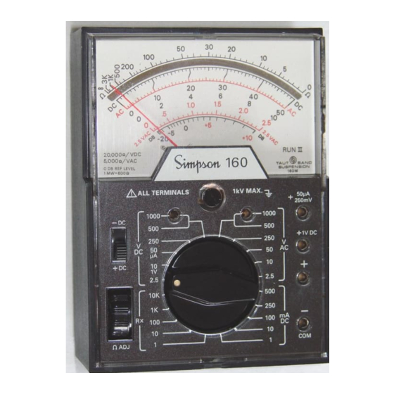
Simpson 160 Operator's Manual
Volt-ohm-milliammeter
Hide thumbs
Also See for 160:
- Operator's manual (32 pages) ,
- Operator's manual (19 pages) ,
- Operator's manual (15 pages)
Table of Contents
Advertisement
Quick Links
Advertisement
Table of Contents

Summary of Contents for Simpson 160
- Page 2 SIMPSON ELECTRIC COM- PANY neither assumes nor authorizes any other persons to assume for it any other liability in connection with the sales of its products.
- Page 3 potential in excess of 30 volts RMS (sine wave) or 42.4 volts DC or peak and where a leakage current from that part to ground exceeds 0.5 milliampere, when measured with an appropriate measuring instrument defined in Sec- tion 11.6.1 of ANSI C39.5.
-
Page 4: Table Of Contents
1. INTRODUCTION …………………………………………………… 5 General ……………………………………………………………….. 5 Suppliers & Accessories ……………………………………………. 5 Safety Consideration ……………………………………………… 5 Technical Data ………………………………………………………... 5 2. INSTALLATION ………………………………………………………. 7 Unpacking & Inspection …………………………………………….. 7 Warranty ………………………………………………………………. 7 Shipping ……………………………………………………………….. 8 Operating Procedure …………………………………………………. 8 3. CONTROLS, CONNECTORS & INDICATORS …………………….. 8 Panel Description …………………………………………………….. -
Page 5: Introduction
Instrument. Supplies & Accessories All supplies and accessories required for the operation of the 160 are fur- nished with each Instrument and listed in Table 1-2. Safety Considerations This Operator’s Manual contains cautions and warnings alerting the user to... - Page 6 * See typical Response Curves, Figure 1-1. ** Per ANSI C39.5 April 1974: “The maximum voltage with respect to ground, which may safely and continuously be applied to the circuit of an instrument.” Direct Current: Ranges: 1, 10, 100, 250, 500 mA; 50 µA on separate jack. Rated Accuracy: Within ±2% full scale, all ranges DC Resistance...
-
Page 7: Installation
00836 Alligator Clip Leads 01927 INSTALLATION This section contains instructions for the installation and shipping of the 160. Included are unpacking and inspection procedures, warranty, shipping, and operating procedure. Unpacking & Inspection Examine the shipping carton for signs of damage before unpacking. Unpack and inspect the Instrument for possible damage in shipment. -
Page 8: Shipping
will be quoted. This charge will not be exceeded without prior approval. Shipping Pack the Instrument carefully and ship it prepaid and insured to the proper destination. Operating Procedure The Instrument may be operated in a horizontal or vertical position. CONTROLS, CONNECTORS &... -
Page 9: Operation
NOTE: When making measurements of the 50 µ A, 250 mV, 1V ranges, the reversing switch must be set to the +DC position to obtain readings. OPERATION Before operating the 160, review the SHOCK HAZARD definition printed on the inside front cover of this manual. Safety Precautions Instruments of this type are intended for use only in low-power, consumer product type applications, such as TV or radio. -
Page 10: Zero Adjustment
“Simpson 160” legend. Measuring DC Voltages, 250 Millivolt Range Use care when making measurements with the 160 on the 250 mV range. An excessive voltage applied when in this range can damage the Instrument. -
Page 11: Measuring Dc Voltages, 1 V Range
Connect the black test lead into the COM (–) jack and the red test lead into the +50 µ A +250 mV jack. Set polarity switch to the + DC position. Set the Range Selector Switch to the 50 µ A position (common to the 50 VDC position). -
Page 12: Measuring Dc Voltages, 1,000 Volt Range Only
AC voltage being applied. The Instrument dial, however, is calibrated in terms of RMS voltage, which will be correct for all sinusoidal waveforms. Since the 160 will respond to DC voltage when set on any AC volt NOTE range an external blocking capacitor must be employed where measurements of AC superimposed on DC are encountered. -
Page 13: Measuring Ac Voltages, 1000 Volt Range Only
4.10 Measuring Resistance When resistances are measured, the internal batteries of the 160 furnish power for the measuring circuit. Correction for battery deterioration over long peri- ods of time is provided by means of the Zero Adjust control which is part of the ohmmeter circuit. -
Page 14: Direct Current Measurement
The resistance of nonlinear components will measure as different val- NOTE: ues on different ranges of the 160. For example, a diode could measure 80 the R x 1 range, and 300 on the R x 10 range. This is normal and is the result of the diode characteristic. -
Page 15: Measuring Direct Current, 0-1 Through 0-500 Ma Ranges
When the Ohms Adjust control cannot be adjusted for zero ohms (with shorted test leads), it is generally an indication that the battery must be replaced. Fail- ure to do so promptly can result in damage to the 160 due to chemical leak- age from the battery. - Page 16 SIMPSON ELECTRIC COMPANY 520 Simpson Avenue Lac du Flambeau, WI 54538-0099 (715) 588-3311 FAX (715) 588-3326 Printed in U.S.A. Part No. 05-111658 Edition 17, 10/15 Visit us on the web at: www.simpsonelectric.com...


Need help?
Do you have a question about the 160 and is the answer not in the manual?
Questions and answers