Table of Contents
Advertisement
Advertisement
Table of Contents

Related Manuals for Simpson 260-8P


Summary of Contents for Simpson 260-8P
- Page 1 Simpson 260 Series 8P ® Volt-Ohm-Milliammeters INSTRUCTION MANUAL...
- Page 2 This warranty shall not apply to any instrument or other article of equipment which shall have been repaired or altered outside the SIMPSON ELECTRIC COMPANY factory or authorized service centers, nor which has been subject to misuse, neg- ligence or accident, incorrect wiring by others, or installation or use not in accord with instructions furnished by the manufacturer.
- Page 3 NOTES...
-
Page 4: Table Of Contents
Contents 1. INTRODUCTION ................6 General Description ................6 Overload Protection ................6 Internal Batteries ................7 Overload Circuit Test ................7 Printed Circuit ..................8 Phenolic Case ..................8 Adjust-A-Vue Handle ................8 Test Leads ..................8 Technical Data ..................8 1.10 Definition of Accuracy ............... - Page 5 Battery Replacement ................27 Fuse Replacement ................27 Test Lead Inspection ................28 Care ....................28...
-
Page 6: Introduction
Due to its sensitivity to overloads, the electronic overload protection relay incor- porated in the 260-8P is susceptible to electrostatic fields from high potentials or transients either in the circuit being measured or in nearby circuitry. -
Page 7: Internal Batteries
600V. A Littlefuse Type BLS 2A 600V fuse may be used as a substitute replace- ment. NOTES: If the 260-8P fails to indicate a reading, the 1 Amp or 2 Amp fuse may be burned out. (Refer to paragraph 5.4 for fuse replacement.) Use only the specified fuse type. -
Page 8: Printed Circuit
Printed Circuit Most of the component parts are mounted on a printed circuit board which simpli- fies assembly and maintenance, thus, extending the useful life of the Instrument. Phenolic Case The phenolic case is designed with heavy reinforced walls for maximum durabil- ity and provides excellent protection for the circuit components. - Page 9 DC MICROAMPERES: Range: 0-50μA Voltage Drop: 250mV DC MILLIAMPERES: Ranges: 0-1-10-100-500 mA Voltage Drop (Approx.): 250 mV, 255 mV, 300 mV, 500 mV DC AMPERES: Range: 0-10A Voltage Drop (Approx.): 255mV NOTE: The 10A range is not internally fused. μ *ACCURACY: DC Voltage Ranges: 2% of Full Scale...
-
Page 10: Definition Of Accuracy
Instrument. 1.12 Audio Alarm The 260-8P Audio Alarm is a transducer which will emit an audible sound when the operator of the Instrument intends to quickly determine the continuity of a circuit. -
Page 11: Accessory Ac High Voltage Probe
260-8P as an AC voltage. The Amp-Clamp has a range selector with six positions. Any of the following current ranges can be used with the 260-8P: 5, 10, 25, 50, 100 or 250 amperes. NOTE: Instructions are furnished with each Amp-Clamp. -
Page 12: Shipping
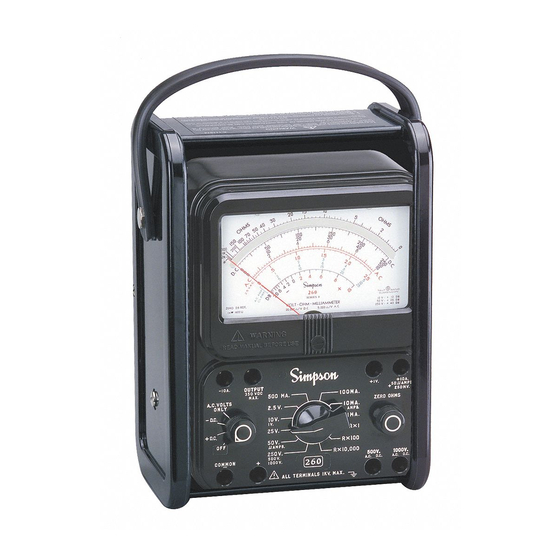
3. CONTROLS, JACKS, AND INDICATORS All operating and adjustment controls, jacks, and indicators for the Simpson 260- 8P are illustrated in this section along with a list (Table 3-1) describing their function. Become familiar with each item before operating the Instrument. - Page 13 -10 A. OUTPUT +10A +1V. AMPS. 350 VDC 500 MA. 100MA. A.C. VOLTS 250 MV. MAX. ONLY 2.5 V. 10MA. ZERO OHMS AMPS. - D.C. 10 V. 1MA. 25 V. R x 1 + D.C. 50 A. R X I00 AMPS.
-
Page 14: Operation
Always refer to the equipment manual and its specific warnings and instructions and observe them as well as those contained herein. The 260-8P should only be used by personnel qualified to recognize shock hazards and trained in the safety precautions required to avoid possible injury. -
Page 15: Polarity Reversing
Do not work alone on high voltage circuits. Make certain that someone ca- pable of giving aid is nearby and alert. Do not handle the Instrument, its test leads, or the circuitry while high voltage is being applied. Hands, shoes, floor, and workbench must be dry. Avoid making measure- ments under humid, damp, or other environmental conditions that could effect the dielectric withstanding voltage of the test leads or Instruments. -
Page 16: Test Leads
Test Leads Test leads are provided with accessory screw-on alligator clips which may be attached to the probe tips. Eliminating the need to hand-hold test prods to a circuit for extended periods, the test clips also reduce hand proximity to a high voltage circuit while energized. -
Page 17: Dc Voltage Measurement 0-2.5 Through 0-250V Range
4.5.3 DC Voltage Measurement 0-2.5 Through 0-250V Range Set the function switch at +DC (Figure 4-2). Plug the black test lead into the -COM- MON jack and the red test lead into the + jack. Set the range switch at one of the five voltage range positions marked 2.5V, 10V, 25V, 50V or 250V. -
Page 18: Dc Voltage Measurement 0-1000V Range
charged. Connect the black test lead to the negative side of the circuit being measured and the red test lead to the positive side of the circuit. Turn on power in circuit being measured. Read the voltage using the 0-50 figures on the black scale marked DC. Multiple the reading by 10. -
Page 19: Ac Voltage Measurement 0-2.5 Thru 0-250V Range
depending upon its waveform, the reading may be higher or lower than the true RMS value of the measured voltage. Thus an error may be introduced if the 260 is used to measure a nonsinusoidal waveform. Also, accuracy is lessened at higher input frequencies (Figure 4-5). -
Page 20: Ac Voltage Measurement 0-500V Range
4.6.2 AC Voltage Measurement 0-500V Range Do not attempt any voltage measurement which may exceed 1000 volts or the circuit-to-ground voltage of the Instrument, 1000 volts maximum. Be sure that the range switch is set to the 250V/500V/1000V range, function switch to AC Volts Only position, and test leads connected to common and 500V jack. -
Page 21: Output Voltage Measurement
Voltage where both AC and DC voltage levels exist. This occurs primarily in amplifier circuits. The 260-8P has a 0.1 mfd, 400 volt capacitor in series with the OUTPUT jack. The capacitor blocks the DC component of the current in the test circuit, but allows the AC or desired component to pass on to the indicating instrument circuit. -
Page 22: Decibel Measurement (-20 To +50 Db)
Some industries measure in terms of voltage or current ratios (decibels) based on a specific reference level. The dB scale on the 260-8P serves this purpose and is calibrated to a reference level (zero dB) or 0.001 watt into 600 ohms. The scale calibration of -20 to +10 dB is for the 0-2.5V range (zero dB = 0.775V). -
Page 23: Direct Current Measurement
NOTE: The maximum voltage ratio that can be measured is +50 dB on the 0-250V range. If dB measurements are being made to a 0.006 watt into 500 ohm reference level, subtract +7 dB from the reading obtained on the 260. Direct Current Measurement Do not change the range setting of the range or function switches while... -
Page 24: Direct Current Measurement 0-10A Range
Positions for Measuring Direct Current The 10A range is not internally fused in the 260-8P. When using the 10A range, never disconnect a test lead from a jack or from the circuit while the circuit is energized. Doing so may damage the test jacks or leads and the arcing may be hazardous to the operator. -
Page 25: Resistance Measurements
4.10 Resistance Measurements Voltage applied to a resistance range will cause reading errors if low and dam- age the Instrument if high. When making in-circuit measurements, make certain that the circuit is completely de-energized before making connections to it. When making in-circuit measurements, circuit paths in parallel with the resis- tance being measured may cause reading errors. -
Page 26: Continuity Tests
Rotate the function switch between the two DC positions to reverse polarity. This will determine if there is a difference between the resistance in the two directions. To check a semiconductor in or out of a circuit (forward and reverse bias resistance measurements) consider the following be- fore making the measurement: The polarity of the internal ohmmeter... -
Page 27: Operator Maintenance
OPERATOR MAINTENANCE The following paragraphs of this section describe battery replacement, fuse re- placement, and preventive maintenance procedures for the 260. Inspection The user is protected from electrical shock by the insulation of the 260 and its test leads. Frequently examine them for any insulation damage such as cracks, cuts, chips, burns or deterioration that expose internal metal parts or reduce the spac- ing between such metal parts and hand contact by the operator. -
Page 28: Test Lead Inspection
Test Lead Inspection Periodic inspection of the test leads is recommended to detect cuts, burned areas, dete- rioration or other damage that could reduce the insulation strength of leads. Care Immediately clean all spilled materials from the Instrument and wipe dry. If the spillage is corrosive, use a suitable cleaner to neutralize the corrosive action. - Page 29 NOTES...
- Page 30 NOTES...
- Page 31 NOTES...
- Page 32 SIMPSON ELECTRIC COMPANY 520 Simpson Avenue Lac du Flambeau, WI 54538 Printed in U.S.A. (715) 588-3311 • FAX (715) 588-3326 Edition 10, 06/17 Visit us on the web at: www.simpsonelectric.com Part No. 06-114339...
Need help?
Do you have a question about the 260-8P and is the answer not in the manual?
Questions and answers